| CPC F16C 11/04 (2013.01) [G06F 1/1681 (2013.01); E05D 3/122 (2013.01); E05D 3/18 (2013.01); E05Y 2999/00 (2024.05)] | 6 Claims |

|
1. A hinge connectable with two housing shells for permitting relative folding and unfolding of the housing shells, comprising:
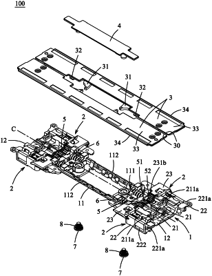
a fixed seat extending in a front-rear direction and having two elongated sides which extend in the front-rear direction and which are opposite to each other in a left-right direction, and two first guideways which are disposed at two sides of a centerline between said two elongated sides, respectively, and which are arcuate;
at least two rotating units disposed at said two sides of said centerline adjacent to said first guideways, respectively, and connectable with the housing shells, respectively, said rotating units being shiftable between an open state and a closed state, each of said rotating units including
a linking member having a linking body, a first arcuate key which is disposed on said linking body to be fittingly slidable on a respective one of said first guideway, and a second arcuate key which is disposed on said linking body and which extends in the left-right direction away from said fixed seat, said linking body having a plate supporting surface which faces upwardly,
a sliding member having a sliding body, a second guideway which is disposed on said sliding body and which is arcuate for said second arcuate key to be fittingly slidable on said second guideway, and an inclined sliding portion which is disposed on said sliding body opposite to said second guideway in the front-rear direction, said sliding body having a shell supporting surface on which a respective one of the housing shells is disposed, and which faces upwardly, and
a rotary bracket pivotably mounted on said fixed seat, and having a bracket body and an inclined guiding portion which is disposed on said bracket body and which is fittingly movable on said inclined sliding portion, said bracket body having a bracket toothed portion which is disposed opposite to said inclined guiding portion in the left-right direction, wherein, during shifting of said rotating units from the open state to the closed state, said sliding member is slided relative to said second arcuate key and said inclined guiding portion and is rotated relative to said fixed seat;
two lateral support plates respectively having two inboard plate edges each extending in the front-rear direction, and two support walls extending in the left-right direction from a respective one of said inboard plate edges to terminate at two outboard plate edges, respectively, said support walls being respectively mounted on said plate supporting surfaces of said linking members of said rotating units to be moved with said linking members; and
at least one synchronous driving unit including two inboard pinions which are disposed proximal to the centerline, and two outboard pinions which are disposed distal from the centerline, said inboard pinions and said outboard pinions being arranged in the front-rear direction to mesh with said bracket toothed portions of said rotary brackets and be connected between said rotating units to make synchronous rotation of said rotary brackets in opposite rotational directions,
wherein, in the open state, said lateral support plates are juxtaposed to conceal said fixed seat in an up-down direction, and, in the closed state, said lateral support plates are brought in an upright position and face each other in the left-right direction and a distance between said inboard plate edges of said lateral support plates is larger than a distance between said outboard plate edges of said lateral support plates.
|