| CPC F02K 1/822 (2013.01) [F02K 7/10 (2013.01); F28D 7/163 (2013.01); F05D 2220/10 (2013.01); F05D 2240/14 (2013.01); F05D 2260/213 (2013.01); F28D 2021/0021 (2013.01); F28D 2021/0026 (2013.01)] | 20 Claims |

|
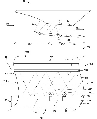
1. A cooling system comprising:
a wall defining a conduit extending from an upstream end to a downstream end, the conduit configured to retain a gas; and
a heat exchanger fluidly coupled with and disposed within a surface of the wall, the heat exchanger having one or more passages fluidly coupled to the conduit and a plurality of internal passages fluidly coupled to the one or more passages;
wherein:
the one or more passages extending between the conduit and the heat exchanger are configured to direct at least a portion of the gas into and out of the heat exchanger,
the plurality of internal passages are configured to direct a cooling fluid and at least a portion of the gas in one or more directions within the heat exchanger;
the heat exchanger is configured to cool the gas within the plurality of internal passages by exchanging heat from the gas within the plurality of internal passages to the cooling fluid within the heat exchanger; and
the conduit is configured to receive a supersonic engine-generated shockwave that impinges on the surface of the conduit at an impingement location.
|