| CPC F01D 11/08 (2013.01) [F01D 9/06 (2013.01); F01D 25/246 (2013.01); F05D 2240/14 (2013.01); F05D 2260/201 (2013.01); F05D 2300/6033 (2013.01)] | 20 Claims |

|
1. A turbine shroud assembly for use with a gas turbine engine, the turbine shroud assembly comprising
a blade track assembly including a blade track segment made of ceramic matrix composite materials and arranged circumferentially at least partway around an axis to define a portion of a path of the turbine shroud assembly, the blade track segment having a shroud wall that extends circumferentially partway around the axis, a first attachment flange that extends radially outward from the shroud wall, and a second attachment flange that extends radially outward from the should wall, the second attachment flange spaced apart axially from the first attachment flange, and
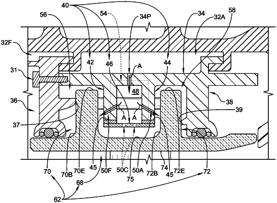
a carrier assembly including a carrier segment made of metallic materials that supports the blade track segment to locate the blade track segment radially outward of the axis and arranged circumferentially at least partway around the axis, the carrier segment having an outer wall, forward and aft walls that extend radially inward from the outer wall axially forward and aft of the first and second attachment flanges, and an intermediate mount that extends radially inward from the outer wall axially between the forward and aft mount flanges of the blade track segment so that the first attachment flange is located in a forward space between the forward wall and the intermediate mount and the second attachment flange is located in an aft space between the intermediate mount and the aft wall,
wherein the intermediate mount is formed to include a cooling chamber that extends circumferentially partway about the axis and impingement passageways in fluid communication with the cooling chamber such that cooling air conducted into the cooling chamber is directed toward the blade track segment to cool the blade track segment during operation of the gas turbine engine, and
wherein at least one of the impingement passageways directs the cooling air axially forward toward the first attachment flange and at least one of the impingement passageways directs the cooling air axially aft toward the second attachment flange.
|