| CPC B66F 7/28 (2013.01) [B66F 7/04 (2013.01); B66F 2700/123 (2013.01)] | 18 Claims |

|
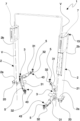
1. A vehicle lift, comprising:
at least one column extending, in use, along a vertical direction,
at least one carriage engaged to the column and slidingly movable along said column, and
at least one lift arm carried by the carriage, wherein said lift arm comprises:
a base body extending between respective first and second end portions of the base body along a respective extension path,
a distal body extending between respective first and second end portions of the distal body along a respective extension path, wherein the distal body is rotatably mounted to the base body for relative rotation about at least one axis, and
a lock configured to selectively block the relative rotation between the base body and the distal body, said lock comprising an insert movable between:
a release position wherein said insert allows relative rotation between the base body and said distal body, and
a gripping position wherein said insert blocks relative rotation between the base body and said distal body,
wherein the insert comprises at least one engagement portion constraining the distal body and blocking relative rotation between the distal body and the base body,
wherein the engagement portion includes at least one tooth configured to cooperate with a toothed profile of the distal body, wherein the toothed profile is defined at the first end portion of the distal body and faces the at least one tooth of the engagement portion, and
wherein said insert is carried by at least one of the base body and the distal body, wherein the insert is slidingly movable with respect to at least one of the base body and the distal body from the gripping position to the release position, and from the release position to the gripping position, along a movement trajectory substantially parallel to at least one of a section of the extension path of the base body and a section of the extension path of the distal body
wherein the insert extends between:
a head surface facing the distal body, and
a bottom surface facing towards the first end portion of the base body,
wherein the engagement portion of the insert emerges from the head surface towards the distal body,
wherein the second end portion of the base body has a seat, wherein the insert is slidingly engaged in the seat along the movement trajectory,
wherein the lock comprises at least one return element in contact, on one side, with the base body and, on another side, with the insert, and wherein the return element is configured to maintain the insert in the gripping position, and
wherein the return element is placed inside the seat of the base body, between a bottom wall of the seat and the bottom surface of the insert.
|