| CPC B65G 47/917 (2013.01) [B25J 9/0093 (2013.01); B25J 9/1697 (2013.01); B25J 15/0683 (2013.01)] | 14 Claims |

|
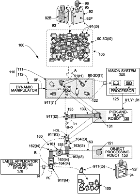
1. A robotic work cell for performing a process on a plurality of objects that are supplied to the robotic work cell in a randomly arranged three-dimensional (3D) cluster, the robotic work cell comprising:
an object separating mechanism including a horizontal surface configured to receive at least a portion of the plurality of objects and a dynamic manipulator configured to apply a separating force such that the received portion forms a two-dimensional (2D) arrangement in which said objects are separated from each other;
a vision system configured to capture current image data from the horizontal surface, to identify a target object of the portion of objects forming the 2D arrangement using the current image data to generate location data operably describing a location of the target object on the horizontal surface, and generating rotational orientation data describing an rotational orientation of the target object;
a first robot mechanism including a first robotic arm that is controlled in accordance with the location data to move the target object from the horizontal surface to a designated hand-off location, and controlled in accordance with the rotational orientation data to rotate the target object into a designated hand-off orientation while moving the target object between the horizontal surface and the designated hand-off location;
a second robot mechanism including a second robotic arm including an end-shaft aligned in a vertical direction;
a carousel robotic end-tool having a central hub fixture that is fixedly connected to the end-shaft and at least one gripper mechanism connected to the central hub fixture such that said gripper mechanism including a pair of gripper structures; and
a processing device operably configured and positioned to perform said process on said target object when said target object is positioned in a designated processing location,
wherein the second robot mechanism is configured to manipulate the carousel robotic end-tool such that the gripper structures of the gripper mechanism are operably positioned in the designated hand-off location to grasp the target object when the target object is moved into the designated hand-off location by the first robot mechanism, and
wherein the second robot mechanism is configured to rotate said carousel robotic end-tool around said vertical direction such that said grasped target object is moved by said gripper mechanism into said designated processing location.
|