| CPC B60T 17/221 (2013.01) [B60T 8/885 (2013.01); G01R 31/3277 (2013.01); B60T 13/746 (2013.01); B60T 2270/406 (2013.01)] | 11 Claims |

|
1. A checking unit for an actuation device of an electrical apparatus, comprising:
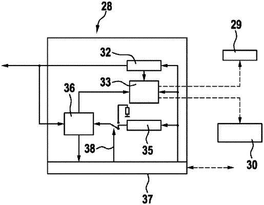
an ASIC configured for connection to at least one signal line of the actuation device, the ASIC including (i) a test circuit configured to generate a voltage test sequence to be applied to the at least one signal line, (ii) a memory configured to store a response pattern from the actuation device in the at least one signal line, and (iii) an evaluation unit configured to compare the response pattern with a reference pattern corresponding to a correct functioning of the actuation device based on the voltage test sequence,
wherein the test circuit includes an internal function checking device configured to check the functionality of the test circuit,
wherein the test circuit includes a first generator configured to generate trigger signals that result in the generation of the voltage test sequence,
wherein the internal function checking device includes a second generator configured to generate a trigger signal pattern that corresponds to the trigger signals, and
wherein the internal function checking device is configured to compare the trigger signals to the corresponding trigger signal pattern and (i) to determine that the test circuit is functional when the trigger signals match the corresponding trigger signal pattern, and (ii) to determine that a fault is present in the test circuit when the trigger signals deviate from the corresponding trigger signal pattern.
|