| CPC B60G 21/051 (2013.01) [B60G 2200/21 (2013.01); B60G 2206/20 (2013.01)] | 5 Claims |

|
1. A vehicle rear suspension structure comprising:
a torsion beam extending in a vehicle width direction; and
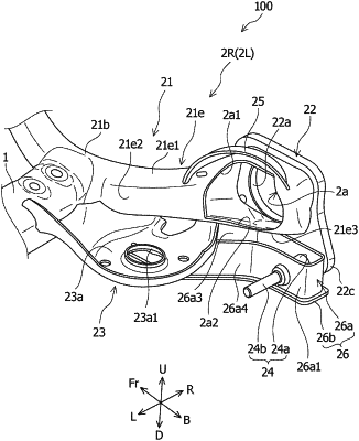
a pair of arm units, one of which is joined to one end of the torsion beam and another of which is joined to another end of the torsion beam, each comprising a trailing arm that has a joining portion with respect to the torsion beam and is formed in a tubular shape extending in a vehicle front-rear direction, and an end plate that occludes a rear side opening of the trailing arm and to which a rear wheel hub is attached,
wherein:
a rear arm, which is a portion of the trailing arm on a rear side with respect to the joining portion, is curved such that the rear side opening is opened to an outer side in the vehicle width direction;
a hole that is open in such a size that an end portion of a drive shaft connectable to the hub can be inserted thereinto is formed in a portion of the rear arm on an inner side in the vehicle width direction; and
each of the units of the pair of arm units comprises an upper reinforcing member that is joined to the rear arm so as to fit at least a part of an upper side edge portion of a peripheral edge portion of the hole, and a lower reinforcing member that is joined to the rear arm so as to fit at least a part of a lower side edge portion of the peripheral edge portion of the hole.
|