| CPC B41J 19/202 (2013.01) [B41J 19/207 (2013.01); B41J 25/001 (2013.01)] | 19 Claims |

|
1. An image forming apparatus, comprising:
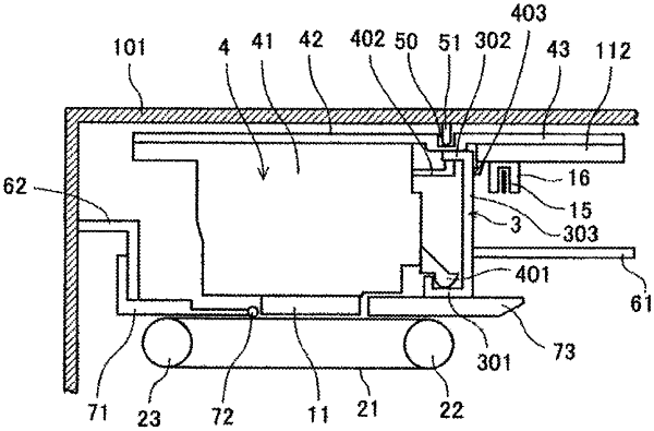
a carriage that is movable in a main scan direction and includes a head mount and a sensor attachment, a head to discharge droplets being mounted to the head mount, and an encoder sensor that extends downward from a bottom surface of the sensor attachment to read an encoder scale;
a guide that is to slidably guide the carriage and that is disposed along the main scan direction, wherein a portion of the guide is disposed along the main scan direction and parallel to a direction perpendicular to a sub scan direction, wherein the sub scan direction is perpendicular to the main scan direction, and the portion of the guide extends downward from and slidably contacting the carriage, and wherein the sensor attachment includes a sliding structure that abuts the guide, and the sliding structure slidably guides the sensor attachment; and
a partition that is fixed and is a distinct structure from the guide and is separated from the guide, wherein
the carriage is movable relative to the partition, and there is a gap between the partition and the carriage,
the portion of the guide and the partition are disposed between the head mount and the encoder sensor in the sub scan direction and the partition has, between the head mount and the encoder sensor, a first face facing in a direction of an encoder sensor side of the partition and a second face, opposite to the first face, facing in a direction of a side of the partition with the head mount, and
the portion of the guide and the encoder sensor overlap in the sub scan direction.
|