| CPC B23Q 17/2485 (2013.01) [G05B 19/4065 (2013.01); B23Q 17/00 (2013.01); B23Q 17/22 (2013.01); B23Q 17/24 (2013.01); G01B 11/02 (2013.01); G01B 11/08 (2013.01); G01B 11/2433 (2013.01); G05B 19/18 (2013.01); G05B 2219/37415 (2013.01)] | 16 Claims |

|
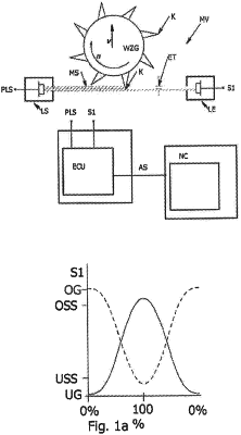
1. A method for checking a tool to be used in a numerically controlled machine tool, with the following steps:
a) provisioning a measuring device, having
a light emitter designed to emit a measuring beam for contactless scanning of the tool by means of the measuring beam, and
a light beam receiver designed to receive the measuring beam and to emit a shadow signal representative of a degree of shading of the measuring beam by the tool;
b) provisioning an evaluation unit designed to receive and process the shadow signal from the light beam receiver;
c) rotating the tool;
d) moving the rotating tool relative to the measuring beam until the tool reaches a starting position in which each cutting edge of the tool dips into the measuring beam so far, and in doing so shading this to such an extent, that a lower and an upper switching threshold of a measurement range of the evaluation unit is reached;
e) moving the tool, which is rotating at a predetermined speed, out of the measuring beam at an at least approximately constant feed rate, starting from said starting position, until a shortest cutting edge falls below the lower switching threshold, and
f) registering the shadow signal produced by each cutting edge of the tool during shading of the measuring beam in relation to a local and a temporal occurrence of the shadow signal during movement of the rotating tool out of the measuring beam;
g) determining an event that at least for one cutting edge of the tool, the shadow signal does not fall below the lower switching threshold of the measurement range and does not exceed the upper switching threshold of the measurement range, so that a maximum shadow signal produced during the movement of the rotating tool out of the measuring beam is located above the lower and below the upper switching threshold of the measurement range; wherein
the feed rate is determined in proportion to said measurement range of the evaluation unit, which range is dependent on a beam transverse measurement of the measuring beam, such that at least one of the cutting edges produces a maximum shadow signal located above the lower and below the upper switching threshold of the measurement range at different positions during at least one revolution of the rotating tool;
on each revolution of the rotating tool, the determined maximum shadow signals of each cutting edge
differ according to a temporal delay of the tool and a spatial change of the tool by an at least approximately constant offset amount, and
are superimposed to form a resultant representative shadow signal for said cutting edge.
|