| CPC B23Q 17/20 (2013.01) | 6 Claims |

|
1. An in-place non-contact detection method for a shaft workpiece, comprising:
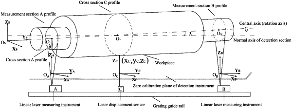
(1) establishing a detection system, calibrating the detection system and establishing a detection coordinate system;
(2) analyzing a pose of a workpiece in the detection system to establish a coordinate system of a workpiece clamping device;
(3) controlling the workpiece clamping device of a shaft workpiece processing machine tool to rotate, continuously acquiring data by a linear laser measuring instrument, and calculating and analyzing acquired data to obtain an ideal reference axis of the shaft workpiece;
(4) continuously acquiring data of a detection part by a laser displacement sensor, and calculating and analyzing the acquired data to obtain actual machining precision of runout of a shaft neck of a camshaft; and
(5) continuously acquiring data of the detection part by adopting the linear laser measuring instrument, and calculating and analyzing the acquired data to obtain machining precision of coaxiality of the shaft workpiece,
wherein specific operations of the step (1) comprises: the detection system comprising a grating guide rail positioned on one side of the machine tool, and a measurement position A, a measurement position C and a measurement position B positioned on the grating guide rail at intervals in sequence, wherein the measurement position A is measured by the linear laser measuring instrument, the measurement position C is measured by the laser displacement sensor, and the measurement position B is measured by the linear laser measuring instrument: the measurement position A and the measurement position B are reference positions required to be detected, and the measurement position C is a position required to be subjected to detection of runout, coaxiality and profile degree: measuring directions of the linear laser measuring instrument and the laser displacement sensor are consistent, a calibration plate is placed at a distance L in front of the measuring directions, and a calibration plane of the calibration plate is adjusted to be orthogonal to a light path of the linear laser measuring instrument and to be perpendicular to a light path of the laser displacement sensor; wherein an XOY plane of the linear laser measuring instrument is parallel to the calibration plane of the calibration plate, the light path of the laser displacement sensor is perpendicular to the XOY plane, and the mounting direction of the laser displacement sensor on the grating guide rail is parallel to the Y axis: a coordinate system OA—XAYAZA and a coordinate system OB—XBYBZB of the linear laser measuring instrument at the position A and the position B are established: then the coordinate systems are adjusted to enable light spots of the laser displacement sensor to be on the Y axis of the light path of the linear laser measuring instrument, and a coordinate system OC—XCYCZC of the laser displacement sensor at the position C is established: if measurement origins of the linear laser measuring instrument are denoted as zero, then the coordinates X and Z of OA and OB are 0; if a measurement origin of the laser displacement sensor is denoted as zero, then the coordinates X and Z of OC are 0;
the linear laser measuring instrument can obtain coordinate data in an XOZ plane, and coordinate data of the Y axis are obtained from the position of the light path of the linear laser measuring instrument on the grating guide rail: the coordinate origin OA of the linear laser measuring instrument at the position A is set as a world coordinate system origin, and if the coordinates of OA are calibrated as (0,0,0), and data measured by the linear laser measuring instrument at the position A are (xA, zA), then three-dimensional coordinates at the position A are (xA, 0, zA);
if a light path distance between the position A and the position B of the linear laser measuring instrument is lAB, then coordinates of OB are calibrated as (0,0, lAB); if data measured by the linear laser measuring instrument at the position B are (xB, zB), then coordinates of the coordinate system OB—XBYBZB in the coordinate system OA—XAYAZA can be expressed as:
 if a light path distance between the position A of the linear laser measuring instrument and the position C of the laser displacement sensor is lAC, then coordinates of OC are calibrated as (0,0, lAC): if data measured by the laser displacement sensor at the position C are (zC), then coordinates of the coordinate system OC—XCYCZC in the coordinate system OA—XAYAZA can be expressed as:
 |