| CPC B23P 15/28 (2013.01) [B23B 27/20 (2013.01); B23K 26/361 (2015.10)] | 1 Claim |

|
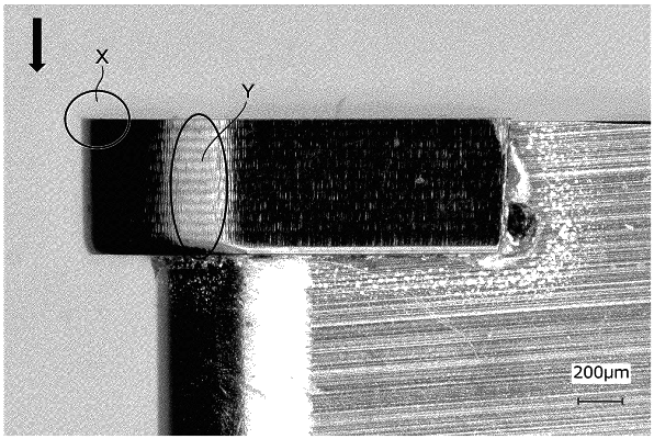
1. A cutting tool having a rake face, a flank face, and an edge having a ridge line interconnecting the rake face and the flank face, wherein on the flank face there is a cutting edge region from the ridge line of the edge to a point away therefrom on the side of the flank face by a distance X,
the distance X being 0.2 mm or more and 5 mm or less,
the cutting edge region having a surface roughness, as represented by an arithmetic mean roughness Ra, of 0.2 μm or less,
the edge having the ridge line without recesses therein of 5 μm or more in size, wherein
a ridge of the edge having the ridge line has a radius of curvature of 1 μm or less,
the material of the cutting tool is nano-polycrystalline diamond, single-crystal diamond, or binderless cBN, and
the cutting edge region on the flank face has no feed marks thereon when observed in multiple fields of view thereon with a laser microscope at a magnification of 10 times the cutting edge region on the flank face.
|