| CPC A63B 69/3635 (2013.01) [A63B 2102/32 (2015.10); A63B 2225/01 (2013.01)] | 10 Claims |
|
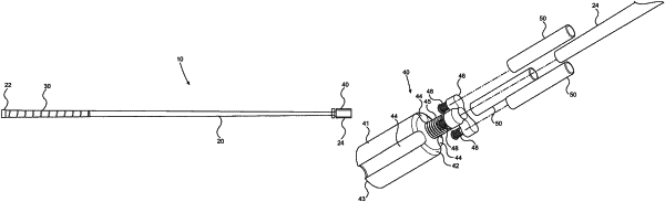
1. A swing speed training club comprising:
(a) a shaft having a butt end and an opposed tip end;
(b) a head portion affixed to the tip end of the shaft, and wherein the head portion is configured so that a mass of the head portion is manually adjustable between a predetermined minimum mass and a predetermined maximum mass without the use of any tool; and wherein:
(c) a line extends centrally through the shaft from the butt end to the tip end defining a shaft central longitudinal axis;
(d) the head portion comprises a generally cylindrical body having a generally circular top, an opposed and generally circular bottom and a circumferential side wall extending between the top and the bottom, wherein a line extending centrally through the body from the top of the body to the bottom of the body defines a body central longitudinal axis;
(e) the body is affixed to the tip end of the shaft so that the tip end of the shaft is adjacent to the top of the body, and the shaft and the body are arranged so that the shaft central longitudinal axis and the body central longitudinal axis are coaxial;
(f) the head portion further comprises three separate and generally cylindrical weights:
(g) the body comprises three weight-receiving chambers, each formed and arranged in the body so as to have an opening at the top of the body and to be at least partially closed at the bottom of the body, each chamber comprising a separate and generally cylindrical side wall, and each of a size corresponding to that of a respective one of the separate cylindrical weights, so that the separate cylindrical weights may each be manually loaded into and manually removed from the respective weight-receiving chambers by way of the chamber openings at the top of the body without the use of any tool;
(h) and wherein the head portion further comprises a keeper at the top of the body that is manually movable without use of any tool, between a first position to load or unload some or all of the three separate cylindrical weights into or from some or all of the three weight-receiving chambers, and a second position to secure each separate cylindrical weight in a respective weight-receiving chamber when it is loaded therein.
|