| CPC A61M 16/0069 (2014.02) [A61M 16/00 (2013.01); A61M 16/024 (2017.08); A61M 16/0616 (2014.02); A61M 16/0666 (2013.01); A61M 16/0683 (2013.01); A61M 16/1045 (2013.01); A61M 16/208 (2013.01); F04D 13/068 (2013.01); F04D 15/00 (2013.01); F04D 17/162 (2013.01); F04D 17/164 (2013.01); F04D 29/281 (2013.01); F04D 29/30 (2013.01); F04D 29/424 (2013.01); F04D 29/444 (2013.01); A61M 2016/0027 (2013.01); A61M 2016/0033 (2013.01); A61M 2205/3341 (2013.01); A61M 2205/8206 (2013.01); A61M 2209/088 (2013.01); A61M 2210/06 (2013.01); F05D 2240/303 (2013.01); F05D 2240/304 (2013.01)] | 42 Claims |

|
1. A respiratory pressure therapy (RPT) system comprising:
a plenum chamber pressurisable to a therapeutic pressure of at least 6 cmH2O above ambient air pressure;
a seal-forming structure constructed and arranged to form a seal with a region of the patient's face at or surrounding an entrance to the patient's airways such that a flow of air at said therapeutic pressure is delivered to at least the entrance to the patient's nares, the seal-forming structure constructed and arranged to maintain said therapeutic pressure in the plenum chamber throughout the patient's respiratory cycle in use;
a positioning and stabilising structure constructed and arranged to provide an elastic force to hold the seal-forming structure in a therapeutically effective position on the patient's head, the positioning and stabilising structure comprising a tie, a lateral portion of the tie being constructed and arranged to overlie a region of the patient's head superior to the otobasion superior in use, and a superior portion of the tie being constructed and arranged to overlie a region of the patient's head in a region of the parietal bone in use, wherein the positioning and stabilising structure has a non-rigid decoupling portion;
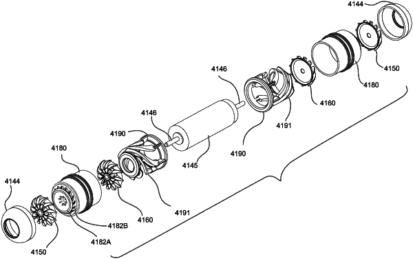
a blower connected to the plenum chamber such that in use the blower is suspended from the patient's head and configured to generate the flow of air and pressurise the plenum chamber to the therapeutic pressure, the blower comprising:
a first side and a second side opposite the first side;
a motor having a first end on the first side of the blower and a second end on the second side of the blower;
a shaft having a first shaft end extending from the first end of the motor and a second shaft end extending from the second end of the motor;
a pair of first impellers and a pair of second impellers, one of the first impellers and one of the second impellers arranged in series on the shaft proximal to the first shaft end and the other of the first impellers and the other of the second impellers arranged in series on the shaft proximal to the second shaft end such that both first impellers and both second impellers are driveable simultaneously by the motor;
a pair of first stators, each of the first stators being positioned on a corresponding one of the first side of the blower and the second side of the blower, each of the first stators being positioned downstream of the first impeller on the corresponding one of the first side of the blower and the second side of the blower along the flow of air generated by the blower in use, and each of the first stators being positioned upstream of the second impeller on the corresponding one of the first side of the blower and the second side of the blower along the flow of air generated by the blower in use;
a pair of second stators, each of the second stators being positioned on a corresponding one of the first side of the blower and the second side of the blower, and each of the second stators being positioned downstream of a corresponding one of the second impellers along the flow of air generated by the blower in use;
a pair of end caps, each of the end caps at least partially enclosing a corresponding one of the first impellers, and each of the end caps at least partially defining a blower inlet;
a pair of blower outlets, each of the blower outlets being positioned downstream of a corresponding one of the second stators; and
a pair of flow paths, each of the flow paths being at least partly formed by the blower inlet at least partially defined by the end cap on a corresponding one of the first side of the blower and the second side of the blower, the first impeller on the corresponding one of the first side of the blower and the second side of the blower, the first stator on the corresponding one of the first side of the blower and the second side of the blower, the second impeller on the corresponding one of the first side of the blower and the second side of the blower, the second stator on the corresponding one of the first side of the blower and the second side of the blower, and the blower outlet on the corresponding one of the first side of the blower and the second side of the blower; and
a power supply configured to provide electrical power to the blower.
|