| CPC A61B 17/07207 (2013.01) [A61B 17/064 (2013.01); A61B 17/068 (2013.01); A61B 17/0682 (2013.01); A61B 17/072 (2013.01); A61B 17/105 (2013.01); A61B 17/320092 (2013.01); A61B 34/30 (2016.02); A61B 50/20 (2016.02); A61B 2017/00017 (2013.01); A61B 2017/00398 (2013.01); A61B 2017/00473 (2013.01); A61B 2017/00734 (2013.01); A61B 2017/0688 (2013.01); A61B 2017/07257 (2013.01); A61B 2017/07271 (2013.01); A61B 2017/07278 (2013.01); A61B 2017/07285 (2013.01); A61B 2017/2923 (2013.01); A61B 2017/2927 (2013.01); A61B 2017/320052 (2013.01); A61B 2017/320093 (2017.08); A61B 2017/320094 (2017.08); A61B 2017/320095 (2017.08); A61B 2017/320097 (2017.08); A61B 2018/0063 (2013.01); A61B 18/1445 (2013.01); A61B 2034/302 (2016.02); A61B 34/37 (2016.02); A61B 50/36 (2016.02)] | 16 Claims |

|
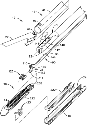
1. A staple cartridge assembly for seating in a channel of a surgical stapling end effector, wherein said staple cartridge assembly comprises:
a cartridge body, comprising:
a proximal end;
a distal end;
a base;
a deck;
a longitudinal slot extending between said proximal end and said distal end;
staple cavities defined in said cartridge body, wherein said staple cavities extend through said deck and said base;
staples removably stored in said staple cavities; and
staple drivers configured to support said staples;
a firing member movable toward said distal end during a staple firing stroke, wherein said firing member is configured to lift said staple drivers toward said deck during said staple firing stroke; and
a pan attached to said cartridge body configured to prevent said staples from falling out of said base of said cartridge body, wherein said pan comprises:
a first lateral pan side attached to said cartridge body;
a second lateral pan side attached to said cartridge body;
a first pan bottom portion extending under a portion of said base from said first lateral pan side; and
a second pan bottom portion extending under a portion of said base from said second lateral pan side;
a pan slot aligned with said longitudinal slot of said cartridge body, wherein said pan slot comprises:
an open proximal pan slot end comprising a first width;
a closed distal pan slot end opposite said open proximal pan slot end; and
a longitudinal portion extending between said open proximal pan slot end and said closed distal pan slot end comprising a second width, wherein said first width is different than said second width.
|