| CPC A61B 17/068 (2013.01) [A61B 17/07207 (2013.01); A61B 17/105 (2013.01); A61B 17/32 (2013.01); A61B 17/3205 (2013.01); G16Z 99/00 (2019.02); A61B 2017/00017 (2013.01); A61B 2017/00154 (2013.01); A61B 2017/00398 (2013.01); A61B 2017/00734 (2013.01); A61B 2017/07271 (2013.01); A61B 2017/07278 (2013.01); A61B 2017/07285 (2013.01); A61B 2017/2923 (2013.01); A61B 2017/2927 (2013.01); A61B 2017/320052 (2013.01)] | 16 Claims |

|
1. A surgical instrument for cutting and stapling tissue, wherein the surgical instrument comprises:
a housing;
a shaft extending from the housing;
an articulation joint;
an end effector rotatably connected to the shaft about the articulation joint, wherein the end effector is configured to staple and cut tissue, and wherein the end effector comprises:
a proximal end adjacent to the shaft and a distal end spaced from the proximal end;
a cutting instrument movable along a cutting travel path to cut the tissue, wherein the cutting travel path comprises:
a forward path in which the cutting instrument moves from the proximal end of the end effector toward the distal end; and
a return path in which the cutting instrument moves to the proximal end;
a channel; and
a replaceable staple cartridge seatable in the channel, wherein the replaceable staple cartridge comprises staples removably stored therein;
a motor;
a power source for providing electrical energy to the motor;
a cutting instrument position sensor for sensing a position of the cutting instrument along the cutting travel path;
a cartridge identification system to identify the cut length of the replaceable staple cartridge;
a motor control circuit connected to the motor and to the power source, wherein the motor control circuit is to receive a signal indicative of the cut length of the replaceable staple cartridge from the cartridge identification system, wherein the motor control circuit controls power levels supplied to the motor from the power source based on the cut length of the replaceable staple cartridge and the position of the cutting instrument along the cutting travel path sensed by the cutting instrument position sensor, such that:
the motor control circuit causes a first current level to be supplied to the motor when the cutting instrument is in a first position range along the forward path of the cutting travel path;
the motor control circuit causes a second current level, which is larger than the first current level, to be supplied to the motor when the cutting instrument is in a second position range along the forward path of the cutting travel path;
a pulse width modulation control circuit for controlling the speed of the cutting instrument; and
a lockout circuit configured to prevent the movement of the cutting instrument along the forward path of the cutting travel path when the replaceable staple cartridge is not seated in the channel;
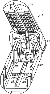
wherein the replaceable staple cartridge comprises a plurality of contacts, and wherein a position of the plurality of contacts is associated with the cut length of the replaceable staple cartridge, wherein the channel comprises a plurality of contact pads positioned to face the replaceable staple cartridge, wherein a subset of the plurality of contact pads are configured to be electrically coupled to a subset of the plurality of contacts on the replaceable staple cartridge when the replaceable staple cartridge is seated in the channel.
|