| CPC A47L 11/4069 (2013.01) [A47L 11/4038 (2013.01); A47L 11/4083 (2013.01); A47L 2201/00 (2013.01)] | 19 Claims |

|
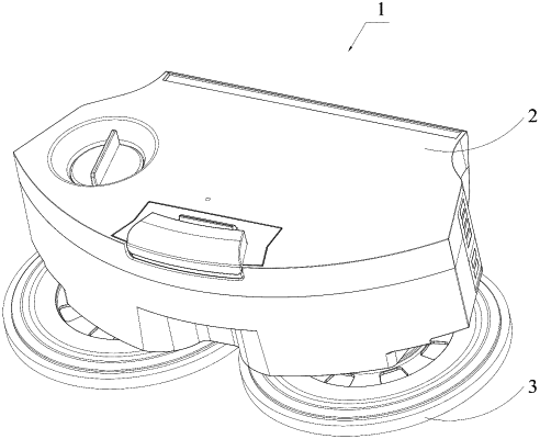
1. A cleaning module, comprising:
a box body defining a liquid cavity for storing cleaning liquid and a receiving cavity separated from the liquid cavity;
at least one driving mechanism comprising at least one drive shaft;
at least one rotating plate assembly, each rotating plate assembly connected to a corresponding drive shaft and comprising a cleaning surface, and the cleaning surface configured to rotate under the drive of the corresponding drive shaft to clean a to-be cleaned surface; and
an air pump mechanism, at least a part of the air pump mechanism positioned in the receiving cavity, and the air pump mechanism comprising:
an air pump positioned in the receiving cavity; and
an air channel communicating with the air pump, the air channel running through a partition wall between the liquid cavity and the receiving cavity, and communicating with the liquid cavity;
wherein when the air pump works, gas is produced and transported via the air channel to the liquid cavity, thus increasing an air pressure in the liquid cavity;
wherein the box body further comprises:
two liquid releasing columns, the two liquid releasing columns being positioned in a bottom of the liquid cavity side by side, an end of each liquid releasing column defining a liquid inlet, and the other end of each liquid releasing column defining a liquid outlet; and
a connection assembly positioned in the liquid cavity and communicated with the liquid inlet of each liquid releasing column, the connection assembly comprising an input end, the input end being lower than a maximum liquid level of the liquid cavity and being configured to receive the cleaning liquid and delivering the cleaning liquid to each liquid inlet.
|