| CPC H05B 45/14 (2020.01) [H05B 45/345 (2020.01); H05B 45/3725 (2020.01)] | 20 Claims |

|
1. A driving circuit for a Light Emitting Diode (LED) lamp, wherein the driving circuit is configured to perform three-stage dimming control on the LED lamp, and the three-stage dimming control is used for controlling the driving circuit to respectively provide three different levels of currents to an LED load of the LED lamp, wherein the driving circuit comprises:
three alternating voltage input terminals, wherein the three alternating voltage input terminals comprise two alternating voltage input terminals for receiving an alternating voltage and one common terminal, the two alternating voltage input terminals are controlled so that at least one alternating voltage input terminal receives the alternating voltage from a power supply;
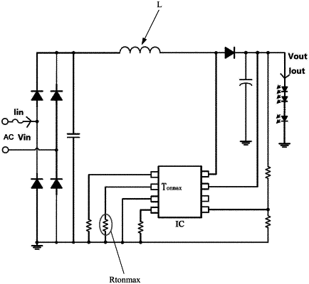
a constant current control circuit, configured to receive the alternating voltage through at least one alternating voltage input terminal and outputting a constant direct current to an LED load, wherein, the constant current control circuit comprises a constant current control chip, and the constant current control chip at least comprises a maximum on-time pin; and
a three-stage dimming detection control circuit, wherein the three-stage dimming detection control circuit comprises a variable control resistor for three-stage dimming control, the three-stage dimming detection control circuit is controlled by the alternating voltage received by at least one alternating voltage input terminal so that the variable control resistor with different resistance values is connected to the maximum on-time pin, and
the constant current control chip is controlled according to a resistance value of the variable control resistor connected to the maximum on-time pin so that the constant current control circuit outputs three different levels of the currents.
|