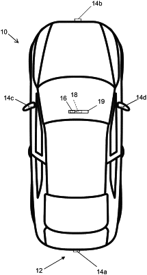
| CPC H04N 23/57 (2023.01) [B60R 11/04 (2013.01); H04N 23/51 (2023.01); B60R 2011/004 (2013.01); B60R 2011/0043 (2013.01)] | 31 Claims |

|
1. A vehicular camera assembly comprising:
a camera housing comprising a first portion and a second portion that is joined with the first portion;
a first printed circuit board (first PCB) and a second printed circuit board (second PCB) disposed in the camera housing;
wherein the first PCB has a first side and a second side separated from the first side of the first PCB by a thickness dimension of the first PCB;
wherein the second PCB has a first side and a second side separated from the first side of the second PCB by a thickness dimension of the second PCB;
wherein the first PCB and the second PCB are stacked and juxtaposed one to the other with the second side of the first PCB opposing the first side of the second PCB;
wherein circuitry of the first PCB is in board-to-board electrically-conductive connection with circuitry of the second PCB;
wherein the circuitry of the first PCB includes an imager disposed at the first side of the first PCB, and wherein the imager comprises a CMOS imaging array having at least one million photosensor elements arranged in columns and rows;
wherein the second PCB includes a circuit board connector disposed at the second side of the second PCB;
an electrical connector disposed at the second portion of the camera housing, wherein the electrical connector comprises a first end and a second end distal from the first end;
wherein the first end of the electrical connector electrically-conductively connects with the circuit board connector at the second side of the second PCB when the second portion of the camera housing is being joined with the first portion of the camera housing;
wherein the first end of the electrical connector comprises a multi-pin connector having at least three individual pins;
wherein the circuit board connector at the second side of the second PCB comprises at least three individual pin-receiving sockets;
wherein, when the second portion of the camera housing is being joined with the first portion of the camera housing, the individual pins of the multi-pin connector of the first end of the electrical connector insert into and electrically-conductively connect to respective individual pin-receiving sockets of the circuit board connector at the second side of the second PCB;
wherein the individual pin-receiving sockets of the circuit board connector are configured to accommodate tolerances when respective individual pins of the multi-pin connector are being inserted into the respective individual pin-receiving sockets of the circuit board connector at the second side of the second PCB when the second portion of the camera housing is being joined with the first portion of the camera housing; and
wherein the second end of the electrical connector is configured to electrically-conductively connect to a vehicle cable when the vehicular camera assembly is installed at a vehicle.
|