| CPC H03M 1/742 (2013.01) [H03M 1/66 (2013.01); H03M 7/165 (2013.01); H04B 1/16 (2013.01)] | 18 Claims |

|
1. A digital-to-analog conversion circuit comprising:
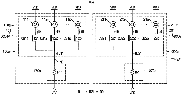
a first digital-to-analog converter (DAC) comprising:
a first binary-to-thermometer code converter (BTC) configured to convert a first digital code received through a first input terminal to a first thermometer code;
a plurality of first current cells connected between a first voltage source and a first output node, and configured to provide a first current to the first output node based on the first thermometer code; and
a first current-to-voltage converter directly connected between the first output node and a second voltage source; and
a second DAC comprising:
a second BTC configured to convert a second digital code received through a second input terminal to a second thermometer code;
a plurality of second current cells connected between the first voltage source and the first output node in parallel with the plurality of first current cells, and configured to provide a second current to the first output node based on the second thermometer code; and
a second current-to-voltage converter directly connected between the first output node and the second voltage source in parallel with the first current-to-voltage converter,
wherein the first current-to-voltage converter and the second current-to-voltage converter are configured to convert a sum of the first current and the second current to a first analog voltage corresponding to a weighted sum of the first digital code and the second digital code, and output the first analog voltage at the first output node.
|