| CPC H03F 1/0288 (2013.01) [H03F 1/32 (2013.01); H03F 1/56 (2013.01); H03F 3/19 (2013.01); H03G 3/3036 (2013.01); H03F 2200/102 (2013.01); H03F 2200/222 (2013.01); H03F 2200/451 (2013.01); H03G 2201/307 (2013.01)] | 20 Claims |

|
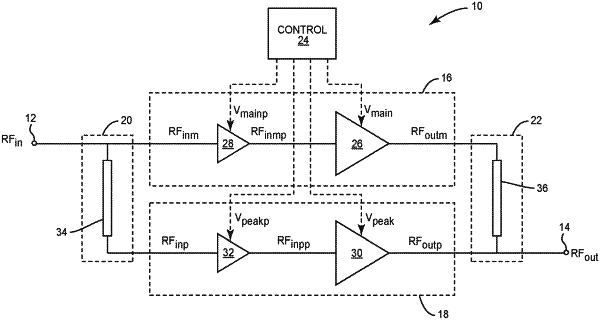
1. Doherty radio frequency (RF) amplifier circuitry comprising:
an input coupler configured to receive one or more RF input signals;
an output coupler configured to output one or more RF output signals;
a main amplifier path between the input coupler and the output coupler, the main amplifier path comprising a main amplifier;
a peaking amplifier path between the input coupler and the output coupler, the peaking amplifier path comprising:
a peaking amplifier; and
a peaking variable gain preamplifier between the input coupler and the peaking amplifier, the peaking variable gain preamplifier configured to adjust a current provided to the peaking amplifier; and
control circuitry configured to adjust a gain of the peaking variable gain preamplifier to compensate for parasitic impedance of the main amplifier and the peaking amplifier.
|