| CPC H01R 13/6471 (2013.01) [H01R 12/585 (2013.01); H01R 12/716 (2013.01); H01R 12/724 (2013.01); H01R 13/02 (2013.01); H01R 13/20 (2013.01); H01R 13/40 (2013.01); H01R 13/504 (2013.01); H01R 13/514 (2013.01); H01R 13/518 (2013.01); H01R 13/6461 (2013.01); H01R 13/6582 (2013.01); H01R 13/6583 (2013.01); H01R 13/6584 (2013.01); H01R 13/6585 (2013.01); H01R 13/6586 (2013.01); H01R 13/6587 (2013.01); H01R 13/6588 (2013.01); H01R 13/6591 (2013.01); H01R 43/24 (2013.01); H05K 1/115 (2013.01); H05K 3/306 (2013.01); H05K 3/3447 (2013.01); H01R 12/71 (2013.01); H01R 12/712 (2013.01); H01R 12/722 (2013.01); H01R 13/46 (2013.01); H01R 13/502 (2013.01); H01R 13/646 (2013.01); H01R 13/6473 (2013.01); H01R 13/6474 (2013.01); H01R 13/6581 (2013.01); H05K 2201/09236 (2013.01); H05K 2201/1078 (2013.01); H05K 2201/10189 (2013.01); H05K 2201/10371 (2013.01); H05K 2201/10871 (2013.01)] | 20 Claims |

|
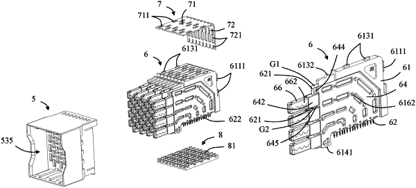
1. A backplane connector, comprising:
a housing comprising a receiving space; and
a plurality of terminal modules mounted to the housing, each terminal module comprising:
a plurality of conductive terminals, each of the conductive terminals comprising a mating portion and a tail portion;
a plurality of metal shield surrounding members which are spaced apart from one another along a first direction and protrude into the receiving space;
a first metal shield located on one side of the plurality of conductive terminals, the first metal shield comprising a first extension portion; and
a second metal shield located on another side of the plurality of conductive terminals, the second metal shield comprising a second extension portion;
wherein the conductive terminals comprise a first signal terminal and a second signal terminal, each of the first signal terminal and the second signal terminal comprises the mating portion and the tail portion, the mating portion of the first signal terminal and the mating portion of the second signal terminal both protrude into the receiving space and are spaced apart from each other along the first direction;
wherein the metal shield surrounding member surrounds a periphery of the mating portion of the first signal terminal and the mating portion of the second signal terminal;
wherein the first extension portion and the second extension portion are electrically connected to the metal shield surrounding member along a second direction perpendicular to the first direction;
wherein each terminal module further comprises an insulating bracket, each conductive terminal comprises a connection portion connecting the mating portion and the tail portion, the connection portions of the conductive terminals are at least partially fixed to the insulating bracket, the mating portion of the first signal terminal and the mating portion of the second signal terminal protrude beyond the insulating bracket in a third direction perpendicular to the first direction and the second direction;
wherein the conductive terminals comprise a first ground terminal and a second ground terminal, and the first signal terminal and the second signal terminal are located between the first ground terminal and the second ground terminal; and
wherein the first metal shield comprises a first elastic arm and a second elastic arm which are located on opposite sides of the first extension portion, respectively; the second metal shield comprises a third elastic arm and a fourth elastic arm which are located on opposite sides of the second extension portion, respectively; the first elastic arm and the third elastic arm are electrically connected to the mating portion of the first ground terminal; and the second elastic arm and the fourth elastic arm are electrically connected to the mating portion of the second ground terminal.
|