| CPC G02B 27/646 (2013.01) [G02B 7/09 (2013.01); G03B 5/00 (2013.01); G03B 13/34 (2013.01); G03B 2205/0007 (2013.01)] | 4 Claims |

|
1. A lens driving device configured to correct a shake by moving a movable part holding a lens barrel in a direction orthogonal to an optical axis, the lens driving device comprising:
a fixing part disposed away from the movable part on an imaging side in an optical axis direction;
a cover configured to cover the movable part at least on a light reception side in the optical axis direction; and
a plurality of suspension wires configured to support the movable part with respect to the fixing part such that the movable part is displaceable in the direction orthogonal to the optical axis, each of the plurality of suspension wires extending along the optical axis direction such that a first end of the suspension wire is fixed to the fixing part and that a second end of the suspension wire is fixed to the movable part,
wherein the movable part includes:
a damper composed of a viscous fluid and disposed so as to make contact with the plurality of suspension wires;
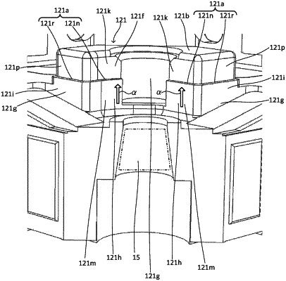
a stopper protrusion provided on a surface on the light reception side such that the stopper protrusion protrudes in the optical axis direction in a region near a portion where the second end of the suspension wire is fixed and that an end of the stopper protrusion faces an inner surface of the cover in the optical axis direction; and
a flow stopper part capable of stopping a flow of the damper flowing toward the end of the stopper protrusion,
wherein:
at the surface on the light reception side of the movable part, the stopper protrusion is provided inside, in a radial direction of the movable part, the portion where the second end of the suspension wire is fixed; and
at a side surface of the stopper protrusion, the flow stopper part is provided at a first side surface that is an outer surface in the radial direction of the movable part and is opposite to the suspension wire,
wherein the flow stopper part comprises one of:
a side stopper step provided at a center part of the first side surface in the optical axis direction;
a groove provided at a center part of the first side surface in the optical axis direction; and
a protrusion provided at a center part of the first side surface in the optical axis direction; and
wherein the flow stopper part serves as a resistance against displacement of the damper toward a front end portion of the stopper protrusion from a base end portion of the stopper protrusion in the optical axis direction along the first side surface of the stopper protrusion.
|