| CPC G02B 6/4455 (2013.01) [G02B 6/444 (2013.01); G02B 6/4452 (2013.01); G02B 6/4478 (2013.01); G02B 6/3897 (2013.01)] | 11 Claims |

|
1. A fiber optic telecommunications device comprising:
a telecommunications frame; and
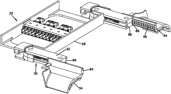
a fiber optic module mounted to the telecommunications frame, the module movable between a retracted position and an extended position with respect to the frame along a sliding direction, the fiber optic module comprising:
a main frame member defining a right side, a left side, and fiber optic connection locations for connecting cables to be routed through the telecommunications frame, wherein the fiber optic connection locations are provided in the form of an array of adapters defining a line which is generally parallel to the sliding direction of the fiber optic module, the adapters being removably mounted to the main frame member;
a rack mount member coupled to each of the right side and the left side of the main frame member, each rack mount member configured for mounting the main frame member to the telecommunications frame;
a center member positioned between the main frame member and the rack mount member at each of the right side and the left side of the main frame member, wherein each center member includes a U-shaped radius limiter defining a curved surface having a vertical height for routing cables with bend radius protection from each of the right and left sides of the main frame member toward each rack mount member; and
a slide assembly provided at each of the right side and the left side of the main frame member for slidably coupling the main frame member to each rack mount member between the extended position and the retracted position along the sliding direction;
wherein the center member is slidable with respect to both the main frame members and the rack mount members and wherein each slide assembly is configured such that movement of the main frame member with respect to the rack mount members simultaneously moves the center members with respect to the rack mount members along the sliding direction,
wherein each slide assembly at the right and left sides is configured such that the center members move at half the linear speed of the main frame member with respect to the rack mount members, each slide assembly including a rotational member that causes the simultaneous movement of the rack mount members, the center members, and the main frame member, the rotational member having an axis of rotation generally perpendicular to the sliding direction of the module, the rotational member being generally vertically aligned with the curved surface of the U-shaped radius limiter of each of the center members such that the rotational member is within the vertical height defined by the curved surface of the U-shaped radius limiter, and
wherein each of the main frame member, the rack mount members at the right and left sides of the main frame member, and the center members at the right and left sides of the main frame member of the fiber optic module includes portions with dovetail profiles for slidable coupling to each other, wherein the portions with dovetail profiles are generally vertically aligned with the curved surface of the U-shaped radius limiter of each of the center members such that the portions with the dovetail profiles are within the vertical height defined by the curved surface of the U-shaped radius limiter.
|