| CPC F16K 99/0017 (2013.01) [B01L 3/502738 (2013.01); B01L 3/502784 (2013.01); B01L 2300/06 (2013.01); B01L 2300/0627 (2013.01); B01L 2300/1827 (2013.01); B01L 2400/0688 (2013.01)] | 16 Claims |

|
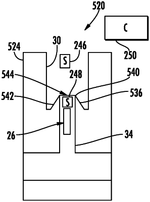
1. A microfluidic valve comprising:
a first portion of a liquid conduit to contain a gas, the first portion including a sensor to detect a flow of a liquid;
a second portion of a liquid conduit to contain the liquid;
a constriction between the first portion and the second portion and across which a capillary meniscus is to form between the gas and the liquid, wherein the constriction is an interface where the liquid conduit undergoes dimensional changes from a larger flow passage to a smaller flow passage and the constriction includes:
a first side wall parallel to a direction of the flow of the liquid,
a second side wall parallel to the first side wall, and
a pillar disposed within the liquid conduit at a location between the first side wall and the second side wall, wherein the pillar extends into the first portion of the liquid conduit;
a drop jetting device within the second portion proximate to the constriction to open the microfluidic valve by breaking the capillary meniscus across the constriction, wherein the drop jetting device includes a resistive element;
a controller to activate the drop jetting device based upon signals from the sensor to break the capillary meniscus across the constriction and in response to the break of the capillary meniscus, to provide continuous flow of the liquid to the first portion from the second portion of the liquid conduit; and
a spout which forms the constriction and part of the second portion and provides an outlet of the second portion to the first portion, the spout having an end projecting into the interior of the first portion to locate the constriction within the first portion, and wherein the drop jetting device is disposed within a portion of the interior of the spout.
|