| CPC F16D 3/223 (2013.01) [B62D 7/16 (2013.01); F16D 3/2233 (2013.01); F16D 2003/22303 (2013.01); F16D 2003/22309 (2013.01); Y10S 464/906 (2013.01)] | 2 Claims |
|
1. A constant velocity joint for a driveline system comprising:
an inner joint part defining a plurality of inner ball races and an outer joint part defining a plurality of outer ball races;
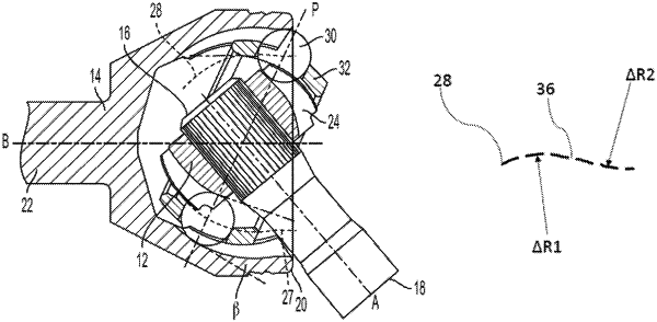
the inner ball races and the outer ball races cooperate to form a plurality of tracks which each define a respective travel path, wherein at least one of the respective travel paths or tracks is defined as a constantly changing curve with a non-continuous radius, wherein the non-continuous radius is defined by a first portion of the travel path and a second portion of the travel path, the first portion and the second portion divided by a transition segment, wherein the first portion and the second portion are symmetrical, inverted opposites of each other; and
a ball located in each of the plurality of tracks,
wherein the constant velocity joint is operatively connectable to a driveshaft component.
|