| CPC F01N 3/225 (2013.01) [F02B 37/183 (2013.01); F02D 41/0007 (2013.01); F02D 41/029 (2013.01); F02D 41/1406 (2013.01); F02D 41/1448 (2013.01); F01N 3/30 (2013.01); F01N 2550/14 (2013.01); F02D 2041/1433 (2013.01); F02D 2200/0406 (2013.01); F02D 2200/0414 (2013.01); F02D 2200/0802 (2013.01); F02D 2200/101 (2013.01); F02D 2200/703 (2013.01)] | 20 Claims |

|
1. A method of estimating secondary air flow in an engine system, the engine system including:
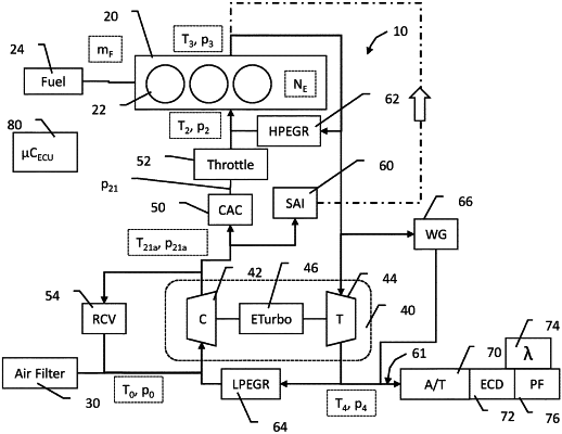
a combustion engine having at least one combustion chamber, an intake manifold having intake manifold pressure and temperature sensors and an exhaust manifold, a turbocharger having a compressor and a turbine configured to provide torque to the compressor, a charge air cooler (CAC), and an aftertreatment system including an environmental catalyst device (ECD), the engine system configured to receive ambient air, compress the ambient air in the compressor, cool the compressed air in the CAC, provide cooled compressed air to the intake manifold, combust a quantity of fuel with the cooled compressed air in the at least one combustion chamber thereby generating exhaust, route the exhaust to the turbine, and route exhaust from the turbine to the aftertreatment system, the engine system also including a secondary air injection (SAI) valve to controllably deliver compressed air from a first location downstream of the compressor to the exhaust at a second location, the SAI valve controlled by an SAI control signal;
the method comprising:
sensing an intake manifold pressure and an intake manifold temperature;
sensing an ambient air pressure, a boost pressure downstream of the CAC, and an engine speed;
calculating a first pressure at the first location using the boost pressure and a CAC flow model;
calculating a first temperature at the first location using a model of the compressor;
calculating an exhaust manifold pressure; and
calculating a mass flow through the SAI valve from a model of the SAI valve using the first pressure, the first temperature, the exhaust manifold pressure, and the SAI control signal as inputs to the model of the SAI valve.
|