| CPC F01D 25/14 (2013.01) [F01D 9/06 (2013.01); F02C 7/18 (2013.01); F02C 9/18 (2013.01); F05D 2220/32 (2013.01); F05D 2240/126 (2013.01); F05D 2240/81 (2013.01); F05D 2260/232 (2013.01); F05D 2260/37 (2013.01)] | 17 Claims |

|
1. A gas turbine engine comprising:
a high pressure turbine system;
a low pressure turbine system;
a mid-turbine frame system arranged axially between the high pressure turbine system and the low pressure turbine system along an engine axis;
a cooling air conduit fluidly connected to the mid-turbine frame system, the cooling air conduit configured to supply a cooling air to the mid-turbine frame system through a conduit outlet; and
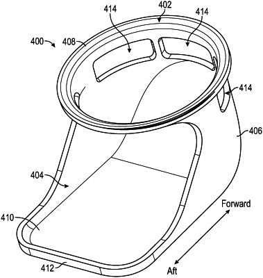
a flow diverter installed at the conduit outlet, the flow diverter having a diverter body comprising:
a connector portion defining a diverter inlet;
a diverter extension at least partially defining a diverter outlet;
a curved portion arranged between the connector portion and the diverter extension, the curved portion configured to change a direction of flow that is a radial flow relative to the engine axis to an axial flow relative to the engine axis as the flow passes from the diverter inlet to the diverter outlet;
at least one diversion slot formed in the diverter body and positioned proximate the connector portion at a location closer to the diverter inlet than the diverter outlet, wherein the at least one diversion slot is configured to direct a portion of the cooling air through the flow diverter to flow in a second direction different from the axial flow, wherein the second direction portion of the cooling air is equal to or less than 50% of a total flow through the flow diverter,
wherein the flow diverter is installed within the conduit outlet such the air passing through the flow diverter is directed aftward toward the low pressure turbine system.
|