| CPC E02F 9/26 (2013.01) [E02F 9/261 (2013.01); E02F 9/267 (2013.01); G06T 1/00 (2013.01); G06T 1/20 (2013.01); H04N 7/18 (2013.01); H04N 7/181 (2013.01); G06T 7/0004 (2013.01); G06V 20/52 (2022.01)] | 20 Claims |

|
1. A surroundings monitoring system for a work machine, comprising:
a memory; and
a processor coupled to the memory, and configured to detect an object present around the work machine,
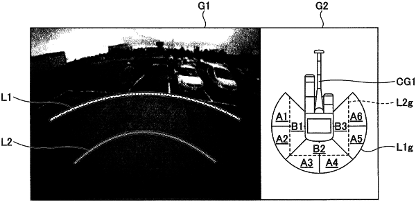
wherein the processor is configured to simultaneously display an image in a first display area and a figure in a second display area different from the first display area on a display apparatus, the image being generated using a captured image of an image capturing apparatus attached to the work machine, the figure including a first figure representing the work machine and a second figure drawn along a periphery of the first figure, the second figure including a first line extending in a first direction away from the first figure, a second line extending in a second direction away from the first figure, and a line extending from an end of the first line to an end of the second line, the second figure being divided into a plurality of regions in a direction away from the first figure,
wherein the processor is configured to highlight a region among the plurality of regions into which the second figure is divided in the direction away from the first figure, without displaying an image of the detected object or a mark indicating the detected object in the region, the region corresponding to a direction of the detected object,
wherein the second figure includes a partial circle and a partial rectangle concentrically inside of the partial circle,
wherein the processor is further configured to display a first distance image and a second distance image over the image in the first display area, the first distance image and the second distance image indicating a first distance and a second distance, respectively, from the work machine, the first distance being different from the second distance,
wherein a circumferential line of the partial circle and a circumferential line of the partial rectangle correspond to the first distance image and the second distance image and indicate the first distance and the second distance, respectively, in the second display area,
wherein the circumferential line of the partial circle includes the line extending from the end of the first line to the end of the second line, and
wherein the circumferential line of the partial rectangle corresponds to a plurality of lines connecting the first line to the second line.
|