| CPC B81B 3/0097 (2013.01) [B25J 15/00 (2013.01); B29C 53/36 (2013.01); B29C 53/80 (2013.01); B81B 2203/053 (2013.01)] | 20 Claims |

|
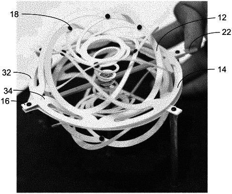
1. A deployable Kiriform flexure, comprising:
a first section of the Kiriform flexure comprising a plurality of fins extending from at least one of a first perimeter ring and a first inner hub and arranged about a central axis; and
a second section of the Kiriform flexure comprising a plurality of fins extending from at least one of a second perimeter ring and a second inner hub and arranged about a central axis, wherein each fin of the second section is joined with a fin of the first section such that the first and second sections share a common central axis in a configuration that produces out-of-plane elastic buckling of the fins to actuate the Kiriform flexure from a substantially flat structure that extends substantially only in two dimensions orthogonal to the central axis to an expanded structure extending substantially in a third dimension parallel to the central axis when at least one of the first and second perimeter rings or inner hubs is rotated relative to the other perimeter ring or inner hub.
|