| CPC B65D 55/16 (2013.01) [B65D 41/3428 (2013.01); B29C 37/0053 (2013.01)] | 22 Claims |
|
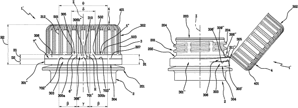
1. A closing cap (1′) for a container (2), comprising a lateral wall (3) extending around an axis (Z) and a transversal wall (4) positioned at one end of the lateral wall (3), a separation line (5″) being provided on the lateral wall (3) to define:
a retaining ring (301″), which is configured to remain anchored to a neck (201) of the container (2) and extends up to a free edge (304); a closing element (302) removably engageable with the neck (201), so as to open or close the container (2); the separation line (5″) extending around the axis (Z) and being circumferentially interrupted to leave the retaining ring (301″) and the closing element (302) joined; wherein the retaining ring (301″) comprises:
a joining portion (305) at which the retaining ring (301″) is joined to the closing element (302);
a first connecting band (306), which extends from a first end zone (305a) of the joining portion (305), and a second connecting band (307), which extends from a second end zone (305b) of the joining portion (305), the second end zone (305b) being positioned circumferentially on the opposite side to the first end zone (305a);
a tab (308″), interposed between the first connecting band (306) and the second connecting band (307) so that, when the closing element (302) is in an open condition and the first and second connecting bands (306, 307) keep the closing element (302) connected to the retaining ring (301″), the tab (308″) rests on the neck (201); wherein the tab (308″) comprises a pair of lateral edges (311″) and a bottom edge (309″), the bottom edge (309″) being aligned, when the closing element (302) is in a closed condition, with a first free lower edge (306′) of the first connecting band (306) and with a second free lower edge (307′) of the second connecting band (307);
wherein, when the closing element (302) is in the closed condition, the bottom edge (309″), the first free lower edge (306′) and the second free lower edge (307′) together define, and lie in, a single plane extending transversely to said axis (Z); and wherein on the lateral wall (3) there are
an incision line (7″) which extends between the separation line (5″) and the free edge (304) of the retaining ring (301″), defines the bottom edge (309″) of the tab (308″), the first free lower edge (306′) of the first connecting band (306) and the second free lower edge (307′) of the second connecting band (307) and is made of a break line of the lateral wall (3);
two cut lines (6″) which define the respective lateral edges (311) of the tab (308″) and are made by cut lines passing through an entire thickness (S) of the lateral wall (3), said two cut lines (6″) not extending below said single plane extending transversely to said axis (Z).
|