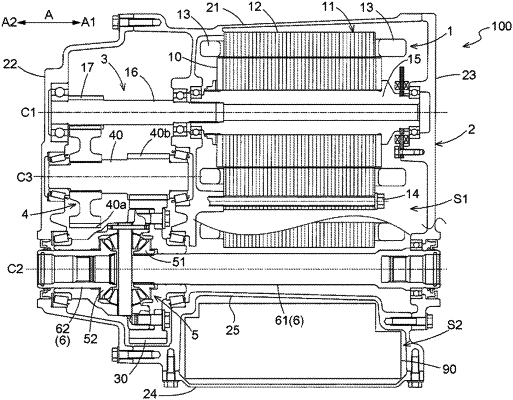
| CPC B60K 17/12 (2013.01) [B60K 17/16 (2013.01); F16H 1/06 (2013.01); F16H 48/08 (2013.01); H02K 7/116 (2013.01)] | 18 Claims |

|
1. A vehicle drive apparatus comprising:
a rotating electrical machine;
a pair of output members that are drivingly coupled to a pair of wheels respectively;
a transmission mechanism that transmits driving force between the rotating electrical machine and the pair of output members; and
an inverter device that controls driving of the rotating electrical machine, wherein
the rotating electrical machine and the pair of output members are separately placed on two axes that are parallel to each other,
the transmission mechanism is provided with an output gear that is drivingly coupled to at least one of the pair of output members and that is placed coaxially with the pair of output members,
a direction in which the rotating electrical machine and the inverter device are arranged side by side in an axial view that is along an axial direction is defined as a first direction,
a direction that is perpendicular to both the axial direction and the first direction is defined as a second direction,
a first output member that is one of the pair of output members is placed between the rotating electrical machine and the inverter device in the first direction, at a position in the second direction where both the rotating electrical machine and the inverter device are placed,
the output gear is placed in such a manner as to overlap each of the rotating electrical machine and the inverter device in the axial view, and
the first output member is placed in such a manner as to overlap the inverter device in a view that is along the second direction.
|