| CPC B32B 37/1009 (2013.01) [B29C 70/44 (2013.01); B32B 37/0046 (2013.01); B65B 31/04 (2013.01); B65D 81/2023 (2013.01); B32B 2309/68 (2013.01)] | 20 Claims |

|
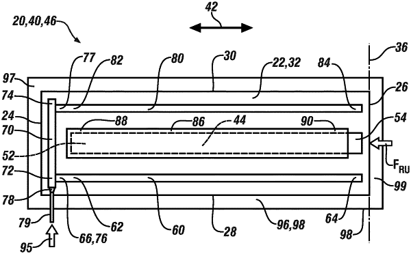
1. A membrane assembly for vacuum bagging, comprising:
an elongate sheet of flexible material having opposed first and second distal ends, opposed first and second longitudinal edges extending generally parallel with each other between the first and second distal ends, and a roll axis defined at the second distal end and oriented generally perpendicular to the first and second longitudinal edges, wherein the elongate sheet is capable of being rolled up about the roll axis into a cylindrical configuration and unrolled from the cylindrical configuration into a flattened-out configuration defining a longitudinal direction parallel to the first and second longitudinal edges;
a bistable tape spring attached to or captured by the elongate sheet and disposed along the longitudinal direction, wherein the bistable tape spring has a first stable state which is a straightened-out state, a second stable state which is a rolled-up state, and a transition state between the first and second stable states; and
a first inflatable tube attached to or captured by the elongate sheet and disposed along the longitudinal direction, the first inflatable tube having a first tube end disposed proximate the first distal end and a second tube end disposed proximate the second distal end, wherein the first inflatable tube is sealed at the second tube end and has an orifice proximate the first tube end for admission of a fluid therethrough for inflation of the first inflatable tube.
|