| CPC B29C 45/14073 (2013.01) [B29C 33/123 (2013.01); B29C 33/424 (2013.01); B29C 45/14819 (2013.01); B29C 45/22 (2013.01); B29C 45/34 (2013.01); B29C 2045/14081 (2013.01); B29L 2031/546 (2013.01)] | 13 Claims |

|
1. A method for molding a golf ball, comprising the steps of:
providing a mold assembly comprising a mold having an upper mold cavity and a lower mold cavity;
wherein each mold cavity has an arcuate inner surface defining an inverted dimple and fret pattern and collectively create a mold having an interior spherical cavity for holding a golf ball subassembly when mated together;
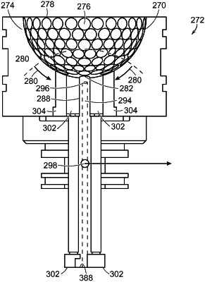
wherein a portion of the inverted dimple and fret pattern is located within a pole region of each mold cavity and comprises at least one mold cavity center vent and a plurality of surrounding mold cavity vents disposed about the at least one mold cavity center vent; each mold cavity center vent and each surrounding mold cavity vent extending through an entire thickness of the mold in the pole region and being adapted to eliminate air produced within the interior spherical cavity during molding;
wherein each mold cavity center vent is sized and shaped to receive a proximal end of a retractable center vent pin; the retractable center vent pin being configured such that air exiting the interior spherical cavity through the mold cavity center vent is drawn along an interior channel of the retractable center vent pin and then exhausted from the mold into the atmosphere outside the mold via an exhaust aperture positioned in a middle section of a length of the retractable center vent pin when sufficient suction is applied;
loading the golf ball subassembly into the interior spherical cavity of the mold;
securing the subassembly within the mold using the retractable center vent pin(s) and a plurality of surrounding retractable pins each being sized and shaped to be received within one of the surrounding mold cavity vents;
injecting a polymeric material into the interior spherical cavity to mold a cover layer about the golf ball sub-assembly within the mold and form a molded golf ball;
withdrawing the retractable center vent pin(s) and surrounding retractable pins before molding is finished; and
separating the upper mold cavity and lower mold cavity and removing the molded golf ball from the mold.
|