| CPC B25F 5/001 (2013.01) [B25B 21/00 (2013.01); B25B 23/14 (2013.01); H02K 7/145 (2013.01)] | 17 Claims |

|
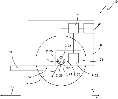
1. A power tool comprising:
a support structure,
a pivot bearing arranged on the support structure,
a shaft mounted on the support structure via the pivot bearing,
a rotatable tool coupled to the shaft,
a strain gauge arrangement for detecting a mechanical vector quantity which depends on a force emanating from the tool, and
a control device adapted to recognize an event and/or a state of the power tool according to the detected mechanical vector quantity,
wherein the strain gauge arrangement is arranged on a stationary structure section coupled in a force-transmitting manner to the pivot bearing and is not arranged on the pivot bearing, wherein the stationary structure section is part of the support structure and/or is arranged directly on the support structure, wherein the strain gauge arrangement comprises a plurality of strain gauges which are distributed on a path running around the shaft, and wherein the strain gauge arrangement is adapted to detect the mechanical vector quantity as an at least two-dimensional vector by measuring a mechanical quantity underlying the mechanical vector quantity in at least two different spatial directions,
wherein the support structure comprises a bearing flange and the stationary structure section is part of the bearing flange, wherein the pivot bearing comprises an outer ring and an inner ring which is mounted so as to be rotatable relative to the outer ring, wherein the shaft is mounted on the inner ring and the pivot bearing abuts with the outer ring against an radially inward facing surface of the bearing flange, wherein the bearing flange has a pivot bearing receptacle section, in which a pivot bearing receptacle is located, in which the pivot bearing is inserted, and the bearing flange further has a collar section adjoining the pivot bearing receptacle section in an axial direction of the shaft, wherein the strain gauge arrangement is arranged on an radially outward facing outer surface of the collar section.
|