| CPC B23B 31/305 (2013.01) [B23B 31/40 (2013.01); B23C 3/055 (2013.01); B23B 51/108 (2013.01); B23B 2270/025 (2013.01)] | 21 Claims |
|
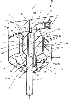
1. A combination tool comprising:
an inner cutting tool configured to machine a first hole region;
an outer cutting tool configured to machine a second hole region, the first hole region being centrally located relative to the second hole region that is located radially outwards relative to the first hole region, the outer cutting tool being sleeve-shaped; and
a tool holder extending along a rotational axis of the combination tool, the rotational axis defining an axial extension, the tool holder comprising:
a tool mounting end section axially located at a distal end of the tool holder and extending radially between the inner cutting tool and the outer cutting tool, the tool mounting end section comprising:
a central tool mounting opening configured for mounting the inner cutting tool;
a distal axial end section of the tool mounting end section;
a section of the tool mounting end section located axially adjacent to the distal axial end section;
a hydraulic chamber formed in the tool mounting end section, the hydraulic chamber configured to contain a hydraulic fluid, the hydraulic chamber comprising:
a second outer hydraulic chamber section formed in the section, the second outer hydraulic chamber section formed ring-shaped and encircling the rotational axis; and
a second inner hydraulic chamber section formed in the section, the second inner hydraulic chamber section formed ring-shaped and encircling the rotational axis;
an outer clamp wall configured to elastically deflect radially outwards, the outer clamp wall comprising:
a second outer peripheral clamp wall section defining the second outer hydraulic chamber section radially outwards;
an inner clamp wall configured to elastically deflect radially inwards, the inner clamp wall comprising:
a second inner peripheral clamp wall section defining the second inner hydraulic chamber section radially inwards;
an annular wall extending radially between the second outer hydraulic chamber section and the second inner hydraulic chamber section; and
a tool mounting peripheral surface surrounding the central tool mounting opening configured for mounting the outer cutting tool;
wherein
the hydraulic chamber is configured to variably set the hydraulic fluid under a hydraulic pressure;
the outer clamp wall and the inner clamp wall define sections of the hydraulic chamber and are configured so that when hydraulic pressure in the hydraulic chamber is increased:
the outer clamp wall elastically deflects outwards, which is configured to exert a clamping force on the outer cutting tool to clamp the outer cutting tool to the tool holder; and
the inner clamp wall elastically deflects inwards, which is configured to exert a clamping force on the inner cutting tool to clamp the inner cutting tool to the tool holder; and
the annular wall is configured to counteract the clamping force exerted by the second outer peripheral clamp wall section on the outer cutting tool and the clamping force exerted by the second inner peripheral clamp wall section on the inner cutting tool.
|