| CPC A61F 2/80 (2013.01) [A61F 2/66 (2013.01); A61F 2/742 (2021.08); A61F 2002/802 (2013.01); A61F 2002/805 (2013.01)] | 13 Claims |
|
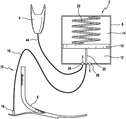
1. A vacuum pump component, comprising:
an elongate compression transfer element; and
a pump housing defining an enclosed space to receive a fluid, the pump housing and a movable wall defining a fluid compartment, the movable wall connected to the compression transfer element, the pump housing forming an interior enclosed space and within the interior enclosed space is the movable wall diving the enclosed space into a fluid chamber and a non-fluid chamber, one side of the movable wall forming the fluid chamber and the opposite side forms the non-fluid chamber, the movable wall arranged to reciprocate within the enclosed space to change the volume of the fluid chamber and the non-fluid chamber;
wherein the compression transfer element comprises: a wire positioned between a first pin and a second pin; the first pin located at the first end of the wire, the first pin being arranged to push the wire towards the housing upon application of a compressive force; and the second pin located at the second end of the wire, the second pin arranged to push the movable wall and increase the volume of the enclosed space upon application of a compressive force on the first pin;
wherein when compressive force is absent, the movable wall rests on a pump housing surface having an input port and output port such that the fluid compartment has zero or near zero volume, the input and output ports being placed opposite the movable wall and on the same side as an opening for the second pin.
|