| CPC A61F 2/64 (2013.01) [A61F 2002/5075 (2013.01); A61F 2002/6836 (2013.01); A61F 2002/701 (2013.01)] | 11 Claims |

|
1. A knee joint, comprising:
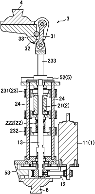
a drive section, a series elastic mechanism, and a crank mechanism, wherein:
the series elastic mechanism comprises a driven member, an elastic member, and a linear motion member;
the driven member is coupled to the drive section and moves in a linear direction when driven by the drive section;
the elastic member is arranged between the driven member and the linear motion member such that the linear motion member is elastically moved by way of the elastic member in the linear direction by movement of the driven member;
the crank mechanism comprises a rotation shaft, a connecting rod, and an arm member, said arm member being rotationally connected to the rotation shaft, and said connecting rod having a first end rotationally connected to the linear motion member and an opposite second end rotationally connected to the arm member, wherein the first end of the connecting rod is displaced by the linear motion member in the linear direction of the movement of the linear motion member and the connecting rod converts linear motion of the linear motion member to rotational motion of the arm member about the rotation shaft; and
the arm member is connected between the second end of the connecting rod and the rotation shaft at an angle α with respect to a vertical axis of the rotation shaft, and the connecting rod is connected to the linear motion member at an angle β with respect to a vertical axis of the linear motion member, wherein the linear motion of the linear motion member is converted to the rotational motion of the arm member according to a reduction ratio that is variable depending on a knee angle of the knee joint, wherein:
the drive section comprises a motor, a transmission, and a ball screw,
the motor is configured to cause rotation of the ball screw in forward and backward directions by way of the transmission, and
the driven member is configured to move linearly in response to rotation of the ball screw, and wherein:
the reduction ratio of the knee joint operates according to the following equation,
 wherein:
Nm is a number of teeth of a motor side pulley of the transmission;
Nb is a number of teeth of a ball screw side pulley of the transmission;
Lb is a lead of the ball screw;
R is a radius of rotation of the arm member; and
K is a reduction coefficient of the crank mechanism.
|