| CPC H04L 27/26132 (2021.01) [H04L 1/0003 (2013.01); H04L 1/0013 (2013.01); H04L 1/08 (2013.01); H04L 1/1861 (2013.01); H04L 5/0048 (2013.01); H04L 5/0051 (2013.01); H04L 5/0053 (2013.01); H04L 5/0094 (2013.01); H04L 25/0224 (2013.01); H04L 25/0228 (2013.01); H04L 27/26 (2013.01); H04L 27/2607 (2013.01); H04L 27/2613 (2013.01); H04L 27/2626 (2013.01); H04W 72/04 (2013.01); H04W 72/0446 (2013.01); H04W 72/20 (2023.01); H04W 72/21 (2023.01); H04W 72/23 (2023.01); H04L 5/005 (2013.01); H04L 27/2636 (2013.01)] | 6 Claims |

|
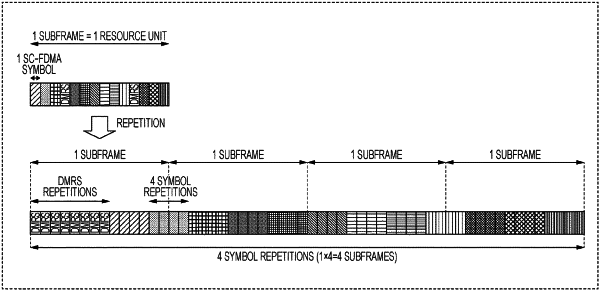
1. An integrated circuit, comprising:
reception circuitry, which, in operation, controls receiving control information indicating a number of symbols on which a Demodulation Reference Signal (DMRS) is to be mapped; and
transmission circuitry, which, in operation, controls transmitting a signal in a multiple consecutive time units, each of the multiple consecutive time units including multiple time slots;
wherein the DMRS is mapped to each of multiple non-consecutive sets in the multiple consecutive time units, a number of symbols in each of the multiple non-consecutive sets being determined based on the control information,
the number of symbols of each of the multiple non-consecutive sets is less than 14 symbols regardless of a number of the multiple consecutive time units,
the symbols of each of the multiple non-consecutive sets are symbols other than sounding reference signal (SRS) symbol candidates, and
a number of the multiple consecutive time units is different for each of numbers of subcarriers to be mapped.
|