| CPC H02K 7/04 (2013.01) [H02K 1/276 (2013.01); H02K 1/28 (2013.01); H02K 21/16 (2013.01)] | 19 Claims |

|
1. A motor comprising:
a rotor including a rotor core provided with a magnet insertion hole and a permanent magnet disposed in the magnet insertion hole, the rotor rotating about an axis of the rotor;
a stator facing the rotor; and
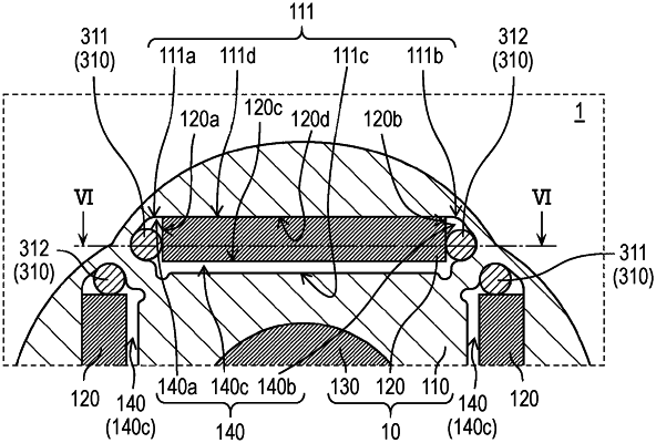
a fixing member fixing the permanent magnet in the magnet insertion hole, the fixing member including a protrusion fitted in a gap between the rotor core and the permanent magnet wherein:
the permanent magnet has a plate shape, and includes:
a first magnet side surface on one side in a width direction of the permanent magnet;
a second magnet side surface on another side in the width direction of the permanent magnet;
a first magnet main surface on one side in a thickness direction of the permanent magnet; and
a second magnet main surface on another side in the thickness direction of the permanent magnet,
the magnet insertion hole has surfaces serving as inner surfaces of the rotor core, the surfaces including:
a first hole main surface located inward in a radial direction intersecting the axis of the rotor core;
a first hole side surface on one lateral side of the magnet insertion hole;
a second hole side surface on another lateral side of the magnet insertion hole; and
a second hole main surface located outward in the radial direction intersecting the axis of the rotor core,
the permanent magnet is disposed in the magnet insertion hole while the first magnet main surface is located inward of the second magnet main surface in the radial direction of the rotor core,
when the rotor is viewed from the direction in which the axis extends, the gap includes:
a first gap between the first magnet side surface and the first hole side surface;
a second gap between the second magnet side surface and the second hole side surface; and
a third gap between the first magnet main surface and the first hole main surface, and
the first protrusion is fitted into the first gap and the second protrusion is fitted into the second gap to fix the permanent magnet to the core.
|