| CPC H02G 1/08 (2013.01) [H04B 17/318 (2015.01)] | 18 Claims |

|
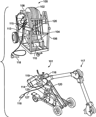
1. A control arrangement for use in a cable installing system, the cable installing system including a first apparatus located at a first endpoint, and a second apparatus located at a second endpoint, the first and second apparatus together configured to install a cable through a conduit between the first endpoint and the second endpoint, the control arrangement comprising:
a first control module located proximate to the first endpoint and operatively coupled to the first apparatus, the first apparatus having an electric motor coupled to a source of power;
a second control module located proximate to the second endpoint and operatively coupled to the second apparatus, the second apparatus having a electric motor coupled to a source of power;
each control module having a wireless communication interface to facilitate wireless communication between the first control module and the second control module;
each control module having a switch input configured to receive an input signal from an operator-activated switch, the input signal indicating either a ready state or a stop state;
each control module further having an apparatus output configured to provide a machine-activation signal or a machine-deactivation signal to the respective first or second apparatus;
wherein the machine-activation signal and the machine-deactivation signal are separate and independent form the source of power that drives the motors of the first second apparatus;
wherein when the first control module receives the input signal from the corresponding operator-activated switch indicating the ready state, the first control module wirelessly transmits a ready signal to the second control module; and
wherein upon receipt of the ready signal by the second control module, and if the second control module receives the input signal from the corresponding operator-activated switch, the second control module wirelessly transmits a start signal to the first control module, and thereafter, both control modules transmit the corresponding machine-activation signal to the correspondingly coupled first apparatus and second apparatus.
|