| CPC H01T 2/02 (2013.01) [H01T 4/10 (2013.01)] | 7 Claims |

|
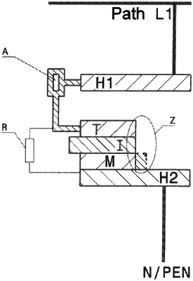
1. An arrangement for firing spark gaps with a trigger electrode (T) which is located at or in one of the main electrodes (H2) and which is insulated from this main electrode (H2), wherein the trigger electrode (T) can be electrically connected to the further main electrode (H1) via at least one voltage-switching or voltage-monitoring element (A) and there is an air gap between the trigger electrode (T) and the further main electrode (H1), wherein the trigger electrode (T) forms a sandwich structure with an insulating layer (I) and a layer made of a material (M) with lower conductivity than the material of one of the main electrodes (H1, H2), the insulating layer (I) is designed as a thin foil or lacquer layer and the layer made of the material (M) of lower conductivity is in contact with one of the main electrodes (H2) or rests on it, characterized in that
for discharging energetically weak overvoltage events without response of the spark gap formed between the main electrodes (H1; H2), the insulating layer (I) of the sandwich structure is interrupted outside the firing area and/or an electrical component which influences the response behavior is connected between the trigger electrode (T) and the main electrode (H2).
|