| CPC H01H 50/18 (2013.01) [H01H 36/00 (2013.01); H01H 50/02 (2013.01)] | 5 Claims |

|
1. A magnetic induction switch, comprising:
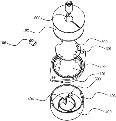
a base (100) with a boss (101);
a mounting chamber (200), arranged at a bottom of the base (100) and having a bottom cover (102) sealing the mounting chamber (200);
an induction circuit board (300), arranged in the mounting chamber (200) and provided with a Hall induction element (301);
a rotating cover (400), rotated and arranged on the base (100) and provided with at least two positioning points (401, 402) on a rotation path;
a magnet (500), arranged in the rotating cover (400), and the magnet (500) changes its position relative to the Hall induction element (301) during rotation of the rotating cover (400) to make the induction circuit board (300) generate a control signal,
wherein the boss (101) is provided with a snap ring (103), and the rotating cover (400) is provided with a clamping connector (403) that cooperates with the snap ring (103).
|