| CPC G02B 6/3821 (2013.01) [G02B 6/387 (2013.01)] | 5 Claims |

|
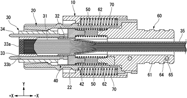
1. An optical connector, comprising:
an optical fiber;
a ferrule with an insertion hole that accommodates the optical fiber;
a housing that accommodates the ferrule and that includes two lock holes formed therein;
two springs that sandwich the optical fiber therebetween, and that bias the ferrule in a forward direction of the optical connector; and
a support portion that supports the two springs from a rear direction of the optical connector, wherein
the support portion comprises:
a first divided member;
a second divided member that is combined with the first divided member; and
two latch portions locked in the two lock holes, and
when the insertion hole extends in the forward and the rear directions, the two springs are disposed along left and right directions of the optical connector, and a vertical direction is orthogonal to the front, rear, right, and left directions, the two latch portions are disposed side by side in the vertical direction and are configured to bend in the vertical direction when locked in the two lock holes.
|