| CPC G01P 15/125 (2013.01) [G01P 15/0802 (2013.01); G01P 15/18 (2013.01); G01P 2015/0848 (2013.01); G01P 2015/086 (2013.01)] | 11 Claims |

|
1. A Micro-Electro-Mechanical-Systems (MEMS) accelerometer, comprising:
a base;
proof mass;
at least one pair of seesaw structures;
an out-of-plane displacement detection component;
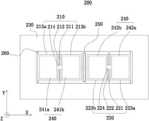
wherein the at least one pair of seesaw structures are oppositely disposed and fixed on the base through anchor points; the out-of-plane displacement detection component is configured to detect rotation of the at least one pair of seesaw structures or out-of-plane linear motion of the proof mass; the at least one pair of seesaw structures is coupled and connected to each other on a first side of the at least one pair of seesaw structures through a first coupling structure, a second side of the at least one pair of seesaw structures coupled and connected to each other by the first coupling structure is respectively provided with a second coupling structure, the first coupling structure and the second coupling structure are elastic coupling structures; wherein the proof mass is connected to the first coupling structure or the proof mass is connected to the second coupling structure; the at least one pair of seesaw structures comprises: a first seesaw structure; and a second seesaw structure;
wherein the first seesaw structure comprises a first anchor point, a first elastic torsion spring, and a first connecting beam; the first anchor point is fixed to the base, the first elastic torsion spring is fixed to the first anchor point, and the first connecting beam is disposed across two sides of the first elastic torsion spring; and a first end of the first connecting beam is connected to the first elastic torsion spring, where the first end is far away from the first coupling structure, and a second end of the first connecting beam is connected to the second coupling structure; the second seesaw structure comprises a second anchor point, a second elastic torsion spring, and a second connecting beam; a first end of the second anchor point is fixed to the base, the second elastic torsion spring is fixed to a second end of the second anchor point, and the second connecting beam is disposed on one side of the second elastic torsion spring; a first end of the second connecting beam is connected to the second elastic torsion spring where the first end of the second connecting beam is far away from the first coupling structure, and a second end of the second connecting beam is connected to the second coupling structure; and the second coupling structure is connected to the proof mass.
|