| CPC G01N 15/06 (2013.01) [G01N 21/05 (2013.01); G01N 21/31 (2013.01); H01L 21/67253 (2013.01); G01N 2015/0053 (2013.01); G01N 15/075 (2024.01); G01N 2021/054 (2013.01)] | 6 Claims |
|
1. A flow cell device comprising:
a flow path through which a fluid medium flows;
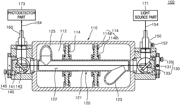
a flow cell part in which the flow path is formed; and
a plurality of elastic pressing parts installed in a housing part to elastically support an outer side surface of the flow cell part; the plurality of elastic pressing parts are disposed in a longitudinal direction of the flow cell part; and each elastic pressing part comprises a pressing rod part,
wherein the flow cell part includes:
a flow cell body part in which the flow path is formed;
a supply pipe part connected to one side of the flow cell body part so that the fluid medium is supplied to the flow cell body part; and
a discharge pipe part connected to the other side of the flow cell body part so that the fluid medium is discharged from the flow cell body part,
further comprising a bubble removal unit which is connected to a fluid medium inlet side of the flow cell part and removes bubbles mixed in the fluid medium introduced into the flow cell part,
wherein the bubble removal unit includes:
a bubble discharge line connected to the fluid medium inlet side of the flow cell part; and
a bubble discharge valve installed on the bubble discharge line, and
wherein one side of the bubble discharge line is connected to a circulation pump installed in a circulation flow path so that the bubbles of the bubble discharge line are discharged to the circulation flow path due to a suction pressure of the circulation pump,
wherein a cross-section area of the flow cell body part is greater than a cross-section area of the supply pipe part so that the fluid medium forms a turbulent flow in the flow cell body part,
wherein the supply pipe part includes:
a first supply pipe part through which the fluid medium is supplied; and
a second supply pipe part formed to have a diameter greater than a diameter of the first supply pipe part so that the fluid medium supplied through the first supply pipe part forms a turbulent flow,
further comprising: a light source part and a photodetector part;
further comprising: a first optical part installed to apply light applied from the light source part onto the fluid medium in the flow cell part;
a second optical part installed to apply light, by which a wavelength of the fluid medium is absorbed while passing through the fluid medium in the flow path, to the photodetector part; and
a third supply pipe part extending from the second supply pipe part and connected to the one side of the flow cell body part,
wherein the third supply pipe part is connected to the flow cell body part so as to be inclined with respect to a longitudinal direction of the flow cell body part, and
wherein the flow cell body part is disposed to be inclined upward from the supply pipe part side to the discharge pipe part side,
further comprising:
a first collimator part which faces the first optical part and to which a first optical fiber part is connected; and
a second collimator part which faces the second optical part and to which a second optical fiber part is connected.
|