| CPC G01B 11/24 (2013.01) [F04D 29/324 (2013.01); G01B 11/002 (2013.01); G01B 11/2504 (2013.01); F05D 2240/303 (2013.01); G01B 11/2513 (2013.01); G01B 11/2518 (2013.01)] | 2 Claims |

|
1. A method for calibrating a rotation center based on a blade local leading-edge curve feature, comprising the following steps:
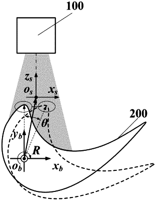
(1) putting a blade onto a turntable plane, and adjusting a pose of a line structured-light sensor such that a laser plane of the line structured-light sensor intersects with a leading-edge curve feature of the blade, the line structured-light sensor acquiring profile data V1∈
 2×n1 of the leading-edge curve feature of the present blade, selecting the maximum value V1m in the profile data V1, and respectively taking n points along left and right sides of the V1m to form a data set v1=[V1m−n . . . V1m . . . V1m+n]1×(2n+1) of a blade local leading-edge curve feature; 2×n1 of the leading-edge curve feature of the present blade, selecting the maximum value V1m in the profile data V1, and respectively taking n points along left and right sides of the V1m to form a data set v1=[V1m−n . . . V1m . . . V1m+n]1×(2n+1) of a blade local leading-edge curve feature;wherein the data set v1 of the blade local leading-edge curve feature is established through the following steps:
selecting the maximum value V1m in the profile data V1, and nth points V1m+n and V1m−n along the left and right sides of the V1m; and calculating a distance dLn from the maximum value V1m to a line connecting the V1m+n and the V1m−n, and selecting the V1m+n and the V1m−n having the dLn more than or equal to an optimal measuring value dz of the line structured-light sensor as endpoints of the blade local leading-edge data set, namely, the profile data set v1=[V1m−n . . . V1m . . . V1m+n]1×(2n+1) of the blade local leading-edge curve feature:
 wherein, dLn is the distance from the maximum value V1m to the line connecting the V1m+n and the V1m−n; and K is a slope of the line connecting the V1m+n and the V1m−n;
(2) ensuring that the pose of the line structured-light sensor is unchanged, the laser plane of the line structured-light sensor still intersects with a leading-edge curve feature of the blade after rotation of the turntable, and a rotation angle θ is 1-3°, acquiring profile data V2∈
 2×n2 of the leading-edge curve feature at this time, first selecting a maximum value V2m in the profile data V2, finding a point V2m-r corresponding to the maximum value V1m in step (1) near the maximum value V2m, respectively taking c reference points V2m-r∈[V2m-c . . . V2m . . . V2m+c]1×(2c+1) along left and right sides of the V2m, and forming a profile data set v2m-r=[V(2m-r)-n . . . V2m-r . . . V(2m-r)+n]1×(2n+1) of a blade local leading-edge curve feature with n points in left and right sides of the V2m-r; 2×n2 of the leading-edge curve feature at this time, first selecting a maximum value V2m in the profile data V2, finding a point V2m-r corresponding to the maximum value V1m in step (1) near the maximum value V2m, respectively taking c reference points V2m-r∈[V2m-c . . . V2m . . . V2m+c]1×(2c+1) along left and right sides of the V2m, and forming a profile data set v2m-r=[V(2m-r)-n . . . V2m-r . . . V(2m-r)+n]1×(2n+1) of a blade local leading-edge curve feature with n points in left and right sides of the V2m-r;(3) calculating covariance matrixes of the profile data sets v1 and V2m-r of the blade local leading-edge curve features, solving eigenvectors and eigenvalues according to the covariance matrixes, and then establishing a matching function M between the maximum values V1m and V2m-r according to the eigenvectors and the eigenvalues:
M(V1m,V2m-r)=Σd=12∥λdr1χdr1−λdr2m(Rθχdr2m)∥2
wherein, λdr1 is the eigenvalue of the covariance matrix of the data set v1; χdr1 is the eigenvector of the covariance matrix of the data set v1; λdr2m is the eigenvalue of the covariance matrix of the data set V2m-r; λdr2m is the eigenvector of the covariance matrix of the data set v2m-r; and
 is a rotation matrix;
(4) constructing c corresponding data sets v2m−r formed by the n points in left and right sides of each of the c reference points V2m−r, finding a reference point V2m−k of the c reference points corresponding to a minimum value in the matching function M, and taking the n points along left and right sides of the reference point V2m−k to form a data set v2=[V(2m-k)-n . . . V2m-k . . . V(2m-k)+n]1×(2n+1) of a blade local leading-edge curve feature; and
(5) respectively solving centroid coordinates v1 and v2 according to the profile data sets v1 and v2 of the blade local leading-edge curve features: vt=(Σi=12n+1vti)/(2n+1), t=1, 2, and v1 and v2 being respectively the centroid coordinates of the data sets v1 and v2 of the blade local leading-edge curve features; and solving a rotation center Ob according to the two centroid coordinates v1 and v2.
|