| CPC F16D 23/06 (2013.01) [F16D 2023/0618 (2013.01); F16D 2023/0656 (2013.01)] | 12 Claims |

|
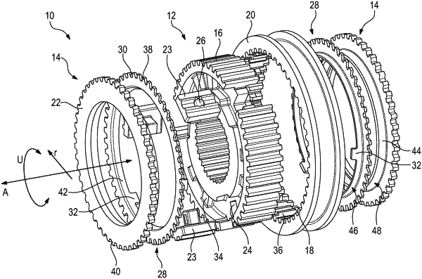
1. A claw-type gearshift, comprising:
a sliding sleeve which is adapted to be axially displaced on a hub body and includes an internal toothing having a multitude of sliding sleeve teeth, and a clutch body of a speed change gear, which includes an external toothing which has a multitude of clutch body teeth and is adapted to engage in the internal toothing of the sliding sleeve, and
a blocking ring which has an external toothing having a multitude of blocking ring teeth and is arranged axially between the hub body and the clutch body and which is fixed to the hub body such that it is rotatable in relation to the sliding sleeve by a certain degree in a circumferential direction between a release position and two locking positions, the locking positions being located on either side of the release position in the circumferential direction,
wherein arranged on the hub body are a plurality of thrust pieces which are movable toward the clutch body, and the blocking ring is adapted to be displaced by the thrust pieces toward the clutch body until a friction surface of the blocking ring comes to rest against a mating friction surface of the clutch body,
wherein the friction surface on the blocking ring and the mating friction surface on the clutch body have a conical shape, and
wherein the blocking ring constitutes a form-locking blockade for the sliding sleeve against a displacement of the sliding sleeve teeth between the clutch body teeth when an axial shifting force is applied in a non-synchronized state, and
wherein the blocking ring teeth and the sliding sleeve teeth are formed such and located opposite each other in the locking position such that when the axial shifting force is applied, the sliding sleeve cannot return the blocking ring to the release position.
|