| CPC F15B 15/2861 (2013.01) [F16K 3/00 (2013.01); F16K 31/06 (2013.01); F16K 37/0041 (2013.01)] | 8 Claims |

|
1. A hydraulic cartridge valve comprising:
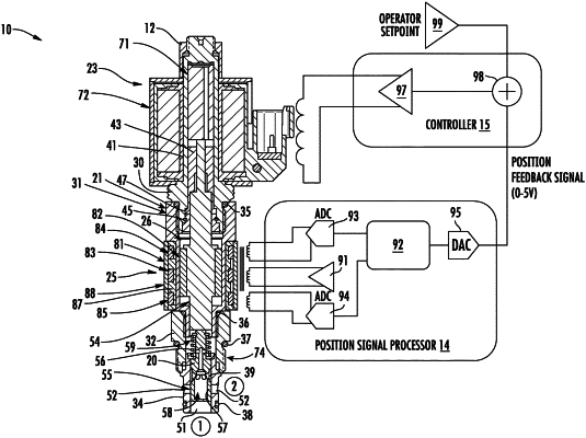
a valve body defining an internal valve cavity, the valve body including a tube assembly, a nonmagnetic pressure vessel, an adapter, and a cage, the tube assembly being connected to the nonmagnetic pressure vessel, the nonmagnetic pressure vessel being connected to the tube assembly and the adapter such that the nonmagnetic pressure vessel is interposed therebetween, the adapter being connected to the nonmagnetic pressure vessel and the cage such that the adapter is interposed therebetween, wherein the tube assembly, the pressure vessel, the adapter, and the cage are hollow and cooperate together to define the internal valve cavity in the form of an axial bore, wherein the cage defines a first port and a second port in fluid communication with the first port via the axial bore;
a movable member axially movable over a range of travel with respect to the valve body, the movable member at least partially disposed within the internal valve cavity over the range of travel, wherein the movable member comprises a nonmagnetic plunger and a metering spool, the nonmagnetic plunger disposed within the tube assembly, the pressure vessel, and the adapter, and the metering spool disposed within the adapter and the cage, the metering spool being axially movable with respect to the cage such that the metering spool is movable over a range of travel between a closed position, in which the metering spool prevents fluid flow from the second port to the first port, and an open position, in which the metering spool defines a fluid flow path between the second port and the first port of the cage;
a position monitoring mechanism arranged with the movable member and configured to detect a position of the movable member over the range of travel and to transmit a position signal indicative of the position of the movable member detected by the position monitoring mechanism;
an actuator arranged with the movable member and configured to selectively move the movable member over the range of travel, the actuator comprises a solenoid assembly including a coil disposed around a valve actuator, the coil mounted to the tube assembly, and the valve actuator disposed within the axial bore of the valve body, the valve actuator being configured to move in response to an electrical current being applied to the coil, the valve actuator being arranged with the nonmagnetic plunger such that the movement of the valve actuator moves the movable member.
|