| CPC F04C 29/126 (2013.01) [F04C 18/0215 (2013.01); F04C 29/124 (2013.01); F16K 15/08 (2013.01); F16L 13/007 (2013.01); F16L 25/0072 (2013.01); F04C 2230/60 (2013.01); F05C 2201/0448 (2013.01); F05C 2201/0475 (2013.01); Y10T 137/7922 (2015.04); Y10T 137/7925 (2015.04); Y10T 137/7929 (2015.04); Y10T 137/7936 (2015.04)] | 10 Claims |

|
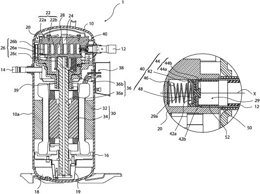
1. A compressor comprising:
a vessel configured to store a lubricating oil therein;
an outer pipe being connected from an outside to pass through the vessel;
an inner pipe being closely inserted into the outer pipe and arranged in the vessel;
a suction pipe being inserted into the outer pipe so as to contact the outer pipe and through which a refrigerant is sucked;
a rotary shaft being accommodated in the vessel; and
a compression mechanism, which is accommodated in the vessel, and configured to compress the refrigerant sucked from the suction pipe through rotation of the rotary shaft;
wherein the compression mechanism includes a suction hole formed of a blind hole to extend in an axial direction of the outer pipe, and the outer pipe is closely inserted into an opening of the suction hole;
wherein the compressor includes a suction valve, which is arranged in the suction hole, and is configured to allow a flow of the refrigerant from the suction pipe into a compression chamber of the compression mechanism;
wherein the suction valve includes a seal on a side facing the opening of the suction hole;
wherein the seal is configured to seal an entire end of the inner pipe on a side facing the suction valve when the compressor stops;
wherein the suction valve comprises:
a suction valve body which is formed in a bottomed cylindrical shape and provided with a hollow part defined therein;
a projection portion which is integrally formed with the suction valve body; and
a spring configured to urge the suction valve body in a direction of sealing the entire end of the inner pipe on the side facing the suction valve;
wherein the projection portion includes a shaft part which is formed on a seal mounting surface for mounting the seal opposite to the hollow part to extend from the seal mounting surface in an axial direction of the suction valve, and a head part which is connected to the shaft part and formed in a plate shape;
wherein the head part is configured to hold the seal with the suction valve body such that the seal and the suction valve body move together in the suction hole;
wherein the seal includes a through hole which is provided at a center portion thereof and into which the shaft part is inserted; and
wherein the projection portion is formed in a cross-sectional T-shape in the axial direction of the suction valve.
|