| CPC F01D 17/145 (2013.01) [F01D 17/26 (2013.01); F01D 21/02 (2013.01); F01D 21/18 (2013.01); F03B 15/18 (2013.01); F05D 2260/904 (2013.01); F05D 2270/021 (2013.01); F05D 2270/091 (2013.01); F05D 2270/64 (2013.01)] | 21 Claims |

|
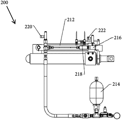
1. A hydraulic lock apparatus for industrial machinery comprising:
a pre-pressurized gas over fluid accumulator;
a differential hydraulic cylinder;
a normally open control valve;
a flow valve which operates as a needle valve in one direction and free flow in the other direction;
a hydraulic actuator; and
wherein the hydraulic lock apparatus is configured to maintain the hydraulic actuator in a reset position until a system failure condition is triggered, and then control the control valve to cause the hydraulic actuator to move to an actuated position.
|
|
19. A method of operating a hydraulic lock apparatus, the hydraulic lock apparatus comprising:
a hydraulic actuator;
a pressure storage device connected to the hydraulic actuator;
a control valve configured to actuate to a first position and a second position;
wherein the control valve fluidly isolates the pressure storage device from the hydraulic actuator when the control valve is in the first position and fluidly connects the pressure storage device to the hydraulic actuator when the control valve is in the second position;
wherein the hydraulic lock apparatus is configured to maintain the hydraulic actuator in a reset position until a system failure condition is triggered, and then control the control valve to cause the hydraulic actuator to move to an actuated position;
the method comprising:
actuating the control valve from the first position to the second position, thereby causing the hydraulic actuator to actuate to an actuated position.
|